Sliding bearing and bearing mechanism having the same

a technology of sliding bearing and bearing mechanism, which is applied in the direction of elastic bearings, rigid support of bearings, transportation and packaging, etc., can solve the problems of low vibration absorption characteristic, high fabrication cost, and stable rolling bearing, so as to reduce linear-motion frictional resistance or frictional torque, small difference in linear-motion frictional resistance, and eliminate the noise of collision

Active Publication Date: 2007-05-22
OILES CORP
View PDF25 Cites 57 Cited by
  • Summary
  • Abstract
  • Description
  • Claims
  • Application Information

AI Technical Summary

Benefits of technology

[0010]The present invention has been devised in view of the above-described aspects, and its object is to provide a sliding bearing and a bearing mechanism having the bearing, which make it possible to eliminate the noise of collision with the shaft such as the column shaft and the rack shaft, make it possible to reduce the linear-motion frictional resistance or the frictional torque, make it possible to make small the difference in the linear-motion frictional resistance or the frictional torque be...

Problems solved by technology

The rolling bearing is stable in the frictional torque, but is inferior in the vibration absorbing characteristic.
Therefore, on top of the fact that the rolling bearing itself is expensive, there is a problem in that the fabrication cost becomes high.
Nevertheless, there is a problem in that since an appropriate clearance (axial gap) is required between the sliding bearing and the column shaft, collision noise occurs between the column shaft and the bearing, and is transmitted to the driver of the automobile as unpleasant sound.
At the same time, the small clearance constitutes a factor hampering the stability in frictional torque, such as the occurrence of variations in frictional torque ...

Method used


Image

  • Sliding bearing and bearing mechanism having the same
  • Sliding bearing and bearing mechanism having the same
  • Sliding bearing and bearing mechanism having the same

Examples


Embodiment Construction

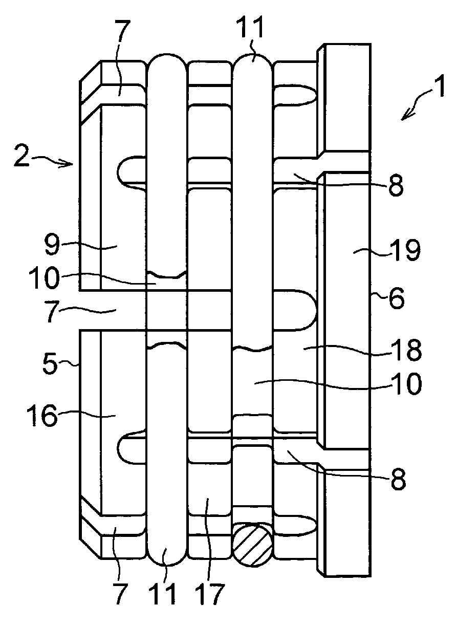
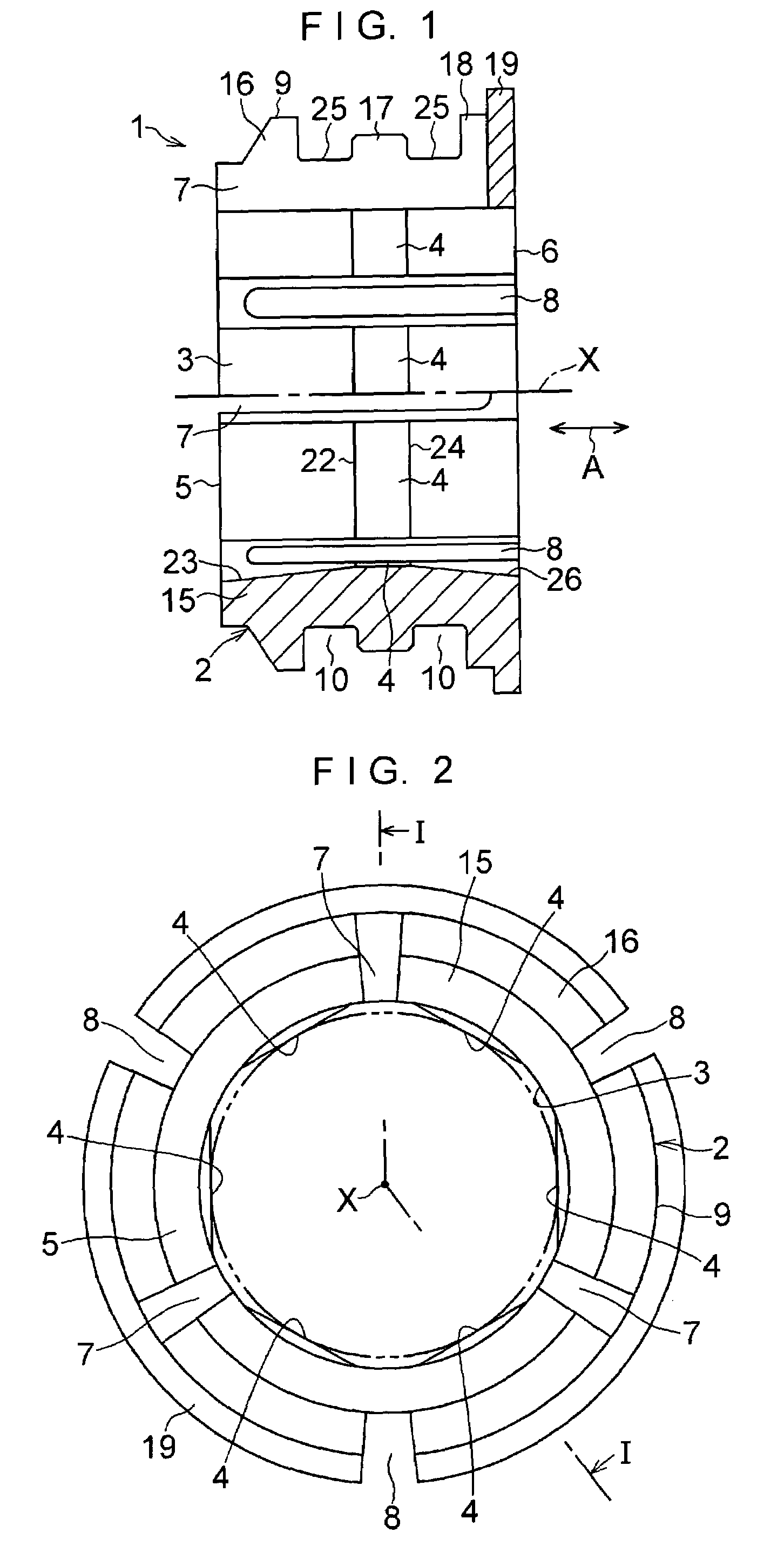
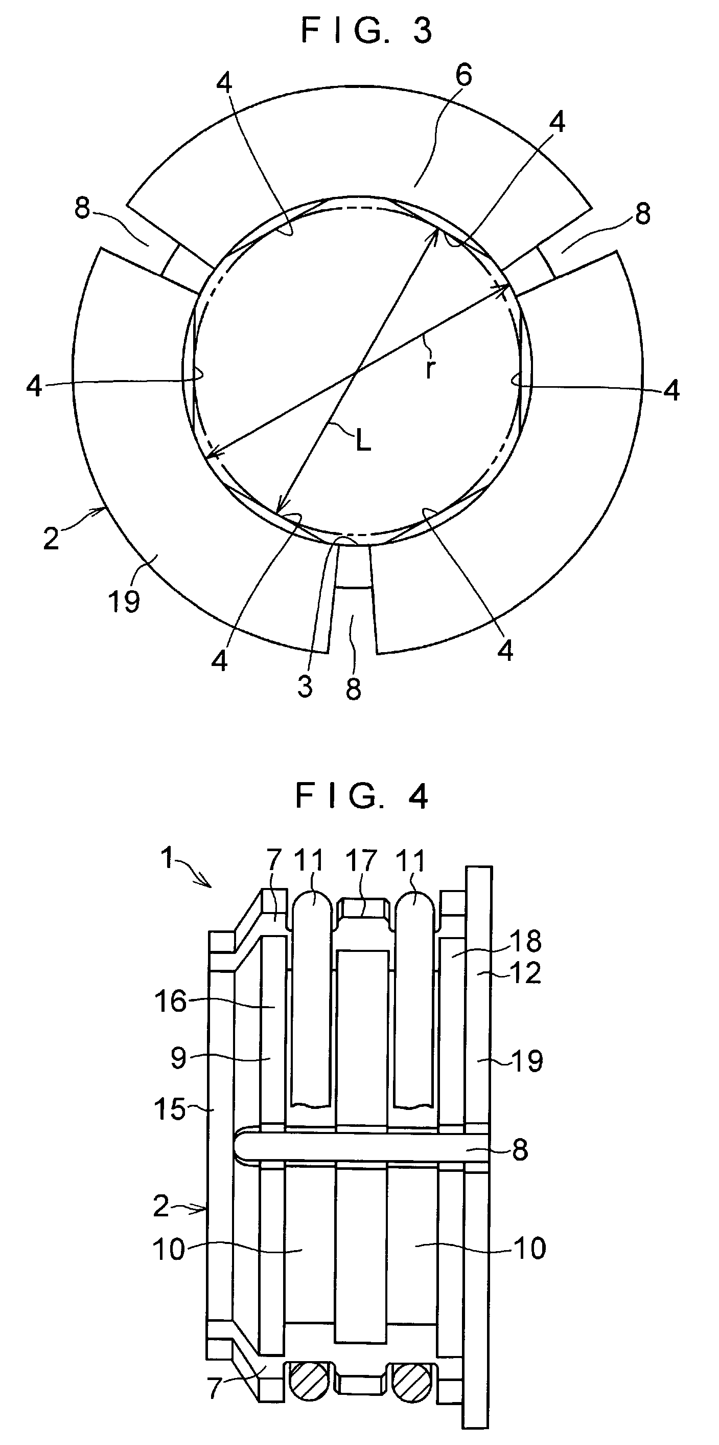
[0054]In FIGS. 1 to 4, a sliding bearing 1 for a steering column in accordance with this embodiment serving as a sliding bearing is comprised of a cylindrical bearing body 2; a plurality of, in this embodiment six, flat surfaces 4 provided on an inner peripheral surface 3 of the bearing body 2 and serving as sliding surfaces; three slits 7 provided in the bearing body 2 and extending in an axial direction A between adjacent ones of the flat surfaces 4 from one end face 5 of the bearing body 2 to this side of the other end face 6 of the bearing body 2; three slits 8 provided in the bearing body 2 and extending in the axial direction A between adjacent ones of the flat surfaces 4 from the other end face 6 of the bearing body 2 to this side of the one end face 5 of the bearing body 2; at least one, in this embodiment two, grooves 10 provided in an outer peripheral surface 9 of the bearing body 2; and at least one, in this embodiment two, elastic rings 11 which are respectively fitted i...


PUM

PropertyMeasurementUnit
Fractionaaaaaaaaaa
Fractionaaaaaaaaaa
Lengthaaaaaaaaaa

Abstract

A sliding bearing for a steering column includes: a cylindrical bearing body; flat surfaces formed integrally on an inner peripheral surface of the bearing body; first slits extending from one end face of the bearing body to this side of the other end face of the bearing body; second slits extending from this side of the other end face of the bearing body to the one end face of the bearing body; grooves formed in an outer peripheral surface of the bearing body; and elastic rings which are respectively fitted in the grooves in such a manner as to project from the outer peripheral surface of the bearing body and to reduce the diameter of the bearing body.

Description

BACKGROUND OF THE INVENTION[0001]1. Field of the Invention[0002]The present invention relates to a sliding bearing interposed between, for example, a steering column tube and a steering column shaft to rotatably support the steering column shaft of an automobile, a sliding bearing interposed between a rack shaft and a tubular member so as to support the rack shaft linearly movably, and a bearing mechanism having such a bearing.[0003]2. Description of the Related Art[0004]As a bearing for a steering column for rotatably supporting a steering column shaft (hereafter referred to as the column shaft) of an automobile, a rolling bearing constituted by a ball bearing or a sliding bearing formed of a synthetic resin is used.[0005]In general, conditions for rotation such as a load and a velocity are not so stringent for the bearing for rotatably supporting the column shaft. However, the vibration absorbing characteristic for absorbing vibrations applied to the column shaft and stability in ...

Claims


Application Information

Patent Timeline
IPC IPC(8): F16C27/06F16C33/02B62D1/16B62D1/185F16C29/02
CPCB62D1/16F16C27/063F16C33/20F16C2326/24F16C2208/60F16C2208/32F16C2208/66F16C2208/78F16C2240/70F16C29/02
Inventor KUBOTA, SHUICHIHORIGUCHI, TAKASHIKAIDA, HIDETOSHI
Owner OILES CORP
Why Eureka
Try Eureka