Low-power low-voltage multi-level variable-resistor line driver

a low-voltage multi-level variable and resistor technology, applied in the field of communication, can solve the problems of high power consumption, high power consumption, and high resistance at the rising output node vsub>op /sub>or vsub>on /sub>, and achieve the effect of high power consumption and improved power efficiency

Inactive Publication Date: 2007-05-22
MARVELL ASIA PTE LTD
View PDF11 Cites 35 Cited by
  • Summary
  • Abstract
  • Description
  • Claims
  • Application Information

AI Technical Summary

Benefits of technology

[0009]The present invention discloses the design of a multi-level PAM driver for high-speed wireline communication, with up to four times improvement in power efficiency over conventional drivers. Two key requirements for high-speed line drivers are first generating the target voltage level onto the controlled-impedance line, and second being impedance-matched to the line itself to eliminate signal reflections from the transmitter back to the line. The driver in accordance with the present invention satisfies both of these requirements at very high power efficiency.

Problems solved by technology

However, in the H-bridge design to keep the current sources in saturation, it requires twice the headroom of a conventional source-coupled design for the current source devices, thus typically requires a higher supply voltage.
However, during the rise period that one of the top switches is shorted, the resistance at the rising output node Vop or Von becomes very low.
Thus, the RC time constant of the rising node gets very low, resulting in a very fast transition.
This difference in the time constants on the two output nodes results in a rather large output common-mode voltage.
Common-mode voltage is not desirable in most wireline applications, especially Ethernet over unshielded twisted pair, as it cause the wire to radiate electromagnetic waves and cause interference that violates FCC regulations.
The requirement for a transformer makes the solution more expensive and less desirable especially for very high-speed application as the transformer cost also goes up with frequency of operation.

Method used


Image

  • Low-power low-voltage multi-level variable-resistor line driver
  • Low-power low-voltage multi-level variable-resistor line driver
  • Low-power low-voltage multi-level variable-resistor line driver

Examples


Embodiment Construction

[0015]The present invention relates generally to the field of communications, and in particular, to line drivers utilized for communications. The following description is presented to enable one of ordinary skill in the art to make and use the invention and is provided in the context of a patent application and its requirements. Various modifications to the preferred embodiment and the generic principles and features described herein will be readily apparent to those skilled in the art. Thus, the present invention is not intended to be limited to the embodiment shown but is to be accorded the widest scope consistent with the principles and features described herein.

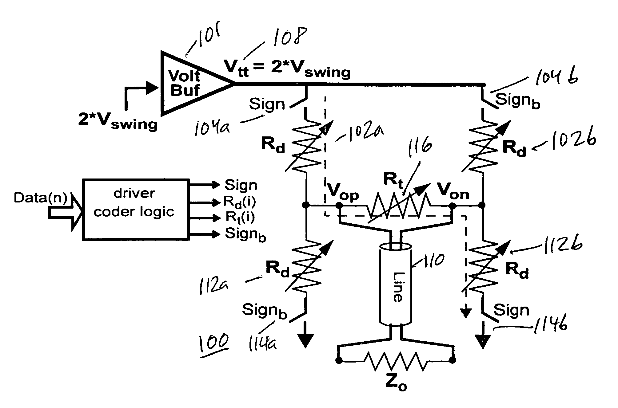
[0016]FIGS. 4A and 4B illustrate two embodiments for a variable-resistor line driver circuit in accordance with the present invention. Both of the embodiments have the capability to generate a continuous range of output signal swings, while maintaining an effective impedance equal to line differential line impedance, Zo. ...


PUM


Abstract

A low-power multi-level pulse amplitude modulation (PAM) line driver using variable resistors is disclosed for transmitting digital data over controlled-impedance transmission lines. This invention discloses the design of a multi-level PAM driver for high-speed wireline communication, with up to four times improvement in power efficiency over conventional drivers. Two key requirements for high-speed line drivers are first generating the target voltage level onto the controlled-impedance line, and second being impedance matched to the line itself to eliminate signal reflections from the transmitter back to the line. The driver in accordance with the present invention satisfies both of these requirements at very high power efficiency.

Description

FIELD OF THE INVENTION[0001]The present invention relates generally to the field of communications, and in particular, to line drivers utilized for communications.BACKGROUND OF THE INVENTION[0002]Communication links require a driver to transmit information into the channel from transmitter to receiver. In wireline communications, the line drivers typically must satisfy two requirements: first generate a certain voltage swing across the transmission line, and second have an output impedance that is matched to the line characteristic impedance to absorb signals arriving at the transmitter and avoid reflections back to the line. In digital data transmission, information is sent using different modulations. One of the most common types of data modulation is pulse amplitude modulation (PAM), where each group of data bits are presented by a voltage level that is transmitted into the channel. Data modems and 100Base-T / 1000Base-T Ethernet transceivers are examples of links that use multi-le...

Claims


Application Information

Patent Timeline
Patent Type & Authority Patents(United States)
IPC IPC(8): H03K3/00H03K17/00H03K17/687H04L25/49
CPCH03K17/6871H03K2217/0036H04L25/028H04L25/4917
Inventor SHIRANI, RAMIN
Owner MARVELL ASIA PTE LTD
Why Eureka
Try Eureka