
VCO with switchable varactor for low KVCO variation

a voltage control and variable technology, applied in the field of analog circuit design, can solve the problems that conventional vco designs may not be able to adapt the vco circuitry to compensa

Active Publication Date: 2007-05-22
AVAGO TECH INT SALES PTE LTD
View PDF3 Cites 38 Cited by
  • Summary
  • Abstract
  • Description
  • Claims
  • Application Information

AI Technical Summary

Benefits of technology

The patent describes a system and method for a VCO (voltage-controlled oscillator) that uses switchable varactors to achieve low KVCO (the variation of the output voltage of the VCO) variation. The technical effect of this invention is to provide a more stable and reliable output signal from the VCO, which can improve the overall performance and reliability of electronic devices that use the VCO.

Problems solved by technology

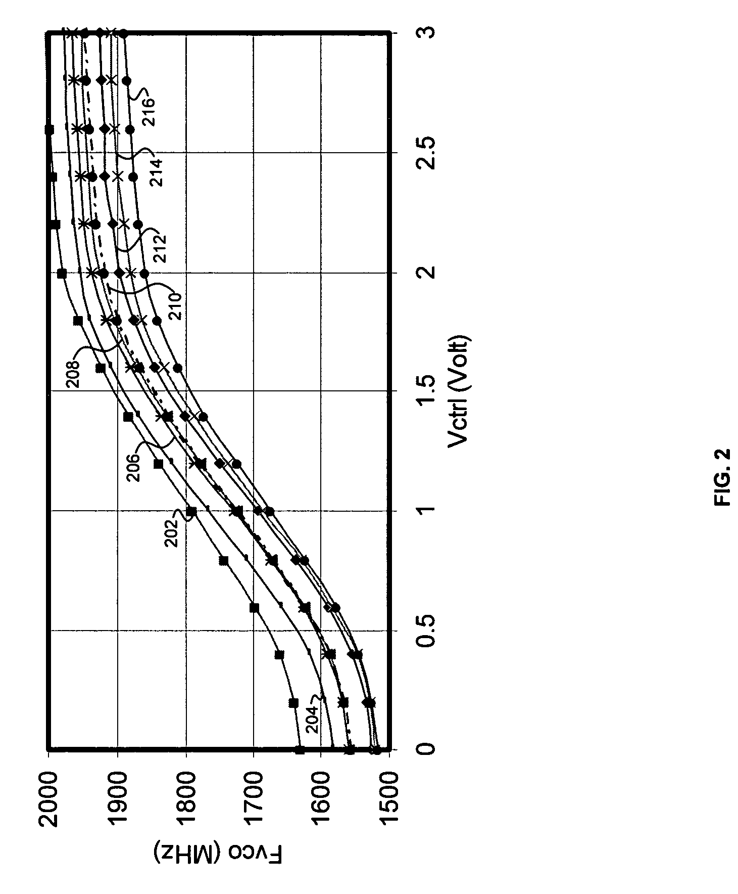
Some conventional VCO designs may not be able to adapt the VCO circuitry to compensate for this plurality of factors such to stabilize values of KVCO, the oscillating frequency of the VCO for a given control voltage level, and the amplitude of the time varying signal generated by the VCO.

Method used


Image

  • VCO with switchable varactor for low KVCO variation
  • VCO with switchable varactor for low KVCO variation
  • VCO with switchable varactor for low KVCO variation

Examples


Embodiment Construction

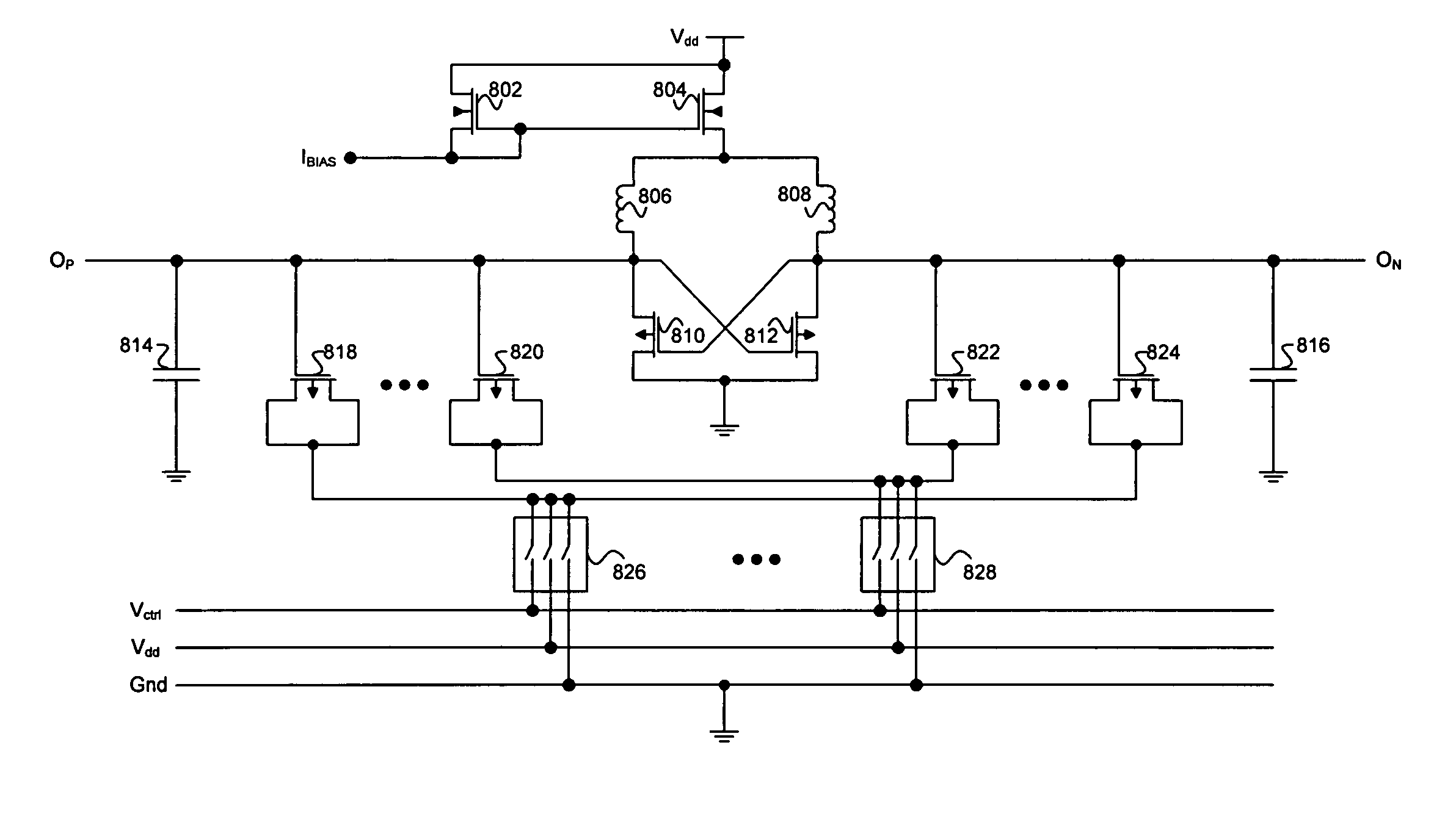
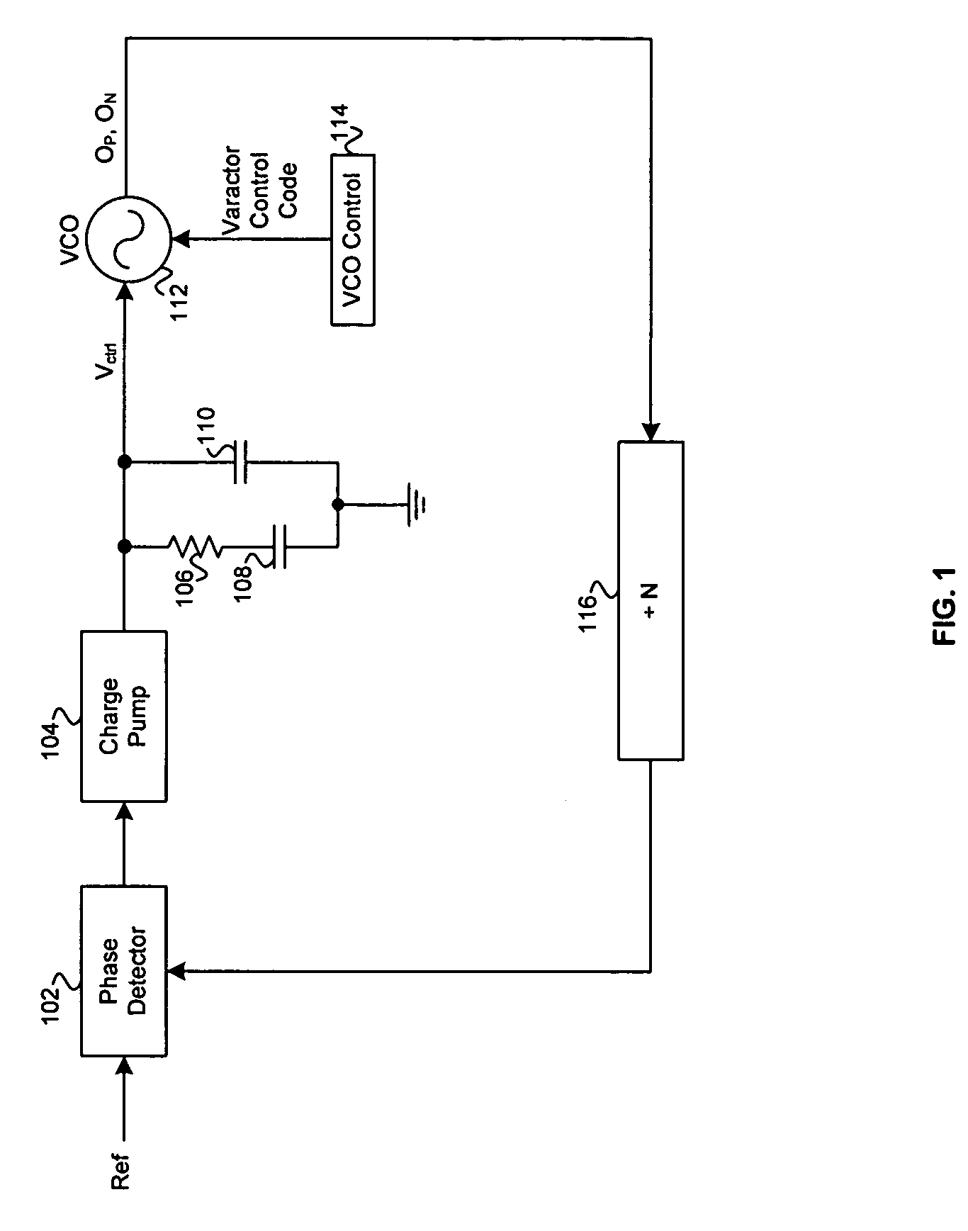
[0018]Certain embodiments of the invention may be found in a method and system for VCO with switchable varactor for low KVCO variation. FIG. 1 is a block diagram of an exemplary phase locked loop (PLL) circuit, in accordance with an embodiment of the invention. Referring to FIG. 1 there is shown a phase detector block 102, a charge pump block 104, a resistor 106, a plurality of capacitors 108 and 110, a voltage controlled oscillator (VCO) 112, a VCO control block 114, and a divide by N (+N) block 116. Also shown in FIG. 1 are a reference signal (Ref), a control voltage signal (Vcntl), a varactor control code, and time varying signals output positive (OP), and output negative (ON). The resistor 106, and plurality of capacitors 108 and 110, may be components in a loop filter. The loop filter may be characterized by an impedance that varies as a function of frequency, Zloop(s), where the variable s may represent the frequency of a signal applied to the loop filter.

[0019]In operation, a...


PUM


Abstract

A method and system for VCO with switchable varactor for low KVCO variation is provided. Aspects of a method for controlling a signal may comprise controlling an oscillating frequency of a time varying signal in a circuit, and controlling a change in the oscillating frequency based on switching of a plurality of varactors. The switching of the varactors may control a change in the oscillating frequency based on a control voltage. The method may further comprise minimizing a change in the rate of change in the oscillating frequency based on the switching of the varactors. Aspects of a system for controlling a signal may comprise circuitry that controls an oscillating frequency of a time varying signal in a circuit, and circuitry that controls a change in the oscillating frequency based on switching of a plurality of varactors. An executable computer program may cause a machine to execute steps as described above.

Description

CROSS-REFERENCE TO RELATED APPLICATIONS / INCORPORATION BY REFERENCE[0001]Not Applicable.FIELD OF THE INVENTION[0002]Certain embodiments of the invention relate to analog circuit design. More specifically, certain embodiments of the invention relate to a method and system for a voltage controlled oscillator (VCO) with switchable varactor for low KVCO variation.BACKGROUND OF THE INVENTION[0003]A circuit that generates a signal for which an oscillating frequency of the signal is proportional to an applied voltage may be known as a voltage controlled oscillator (VCO). A device for which the capacitance value varies based on an applied voltage may be known as a variable reactance, or varactor. The oscillating frequency of a VCO may be controlled by utilizing a varactor. The value of KVCO may control the amount by which the oscillating frequency of a time varying signal generated by a VCO may change based on a change in the voltage level of a control signal. In operation, the value of KVCO...

Claims


Application Information

Patent Timeline
Patent Type & Authority Patents(United States)
IPC IPC(8): H03B5/12
CPCH03L7/099
Inventor CHIEN, HUNG-MING
Owner AVAGO TECH INT SALES PTE LTD
Learn More