Differential signal detector methods and apparatus

a detector and signal technology, applied in the field of differential signal detector methods and apparatuses, can solve the problems of wasting valuable interface pins at the edge of the chip, not addressing the situation of data unintentionally corrupted, and the solution will not work i

Inactive Publication Date: 2007-05-29
ALTERA CORP
View PDF4 Cites 30 Cited by
  • Summary
  • Abstract
  • Description
  • Claims
  • Application Information

AI Technical Summary

Problems solved by technology

However, this solution wastes valuable interface pins at the edge of a chip, and does not address the situation where data is unintentionally corrupted.
However, this solution will not work if any type of automatic gain control is used.
Because of the added redundancy, random errors in the data will tend to violate the coding rules.
Existing signal detectors employing envelope detection are typically common-mode dependent, making them less robust.
Different hardware vendors may use slightly different VCC voltages to indicate a logical high, so it is difficult to design circuitry that can accommodate all vendors.
In addition, absolute voltages are difficult to set precisely, which makes tasks like fixing a reliable threshold voltage more difficult.

Method used


Image

  • Differential signal detector methods and apparatus
  • Differential signal detector methods and apparatus
  • Differential signal detector methods and apparatus

Examples


Embodiment Construction

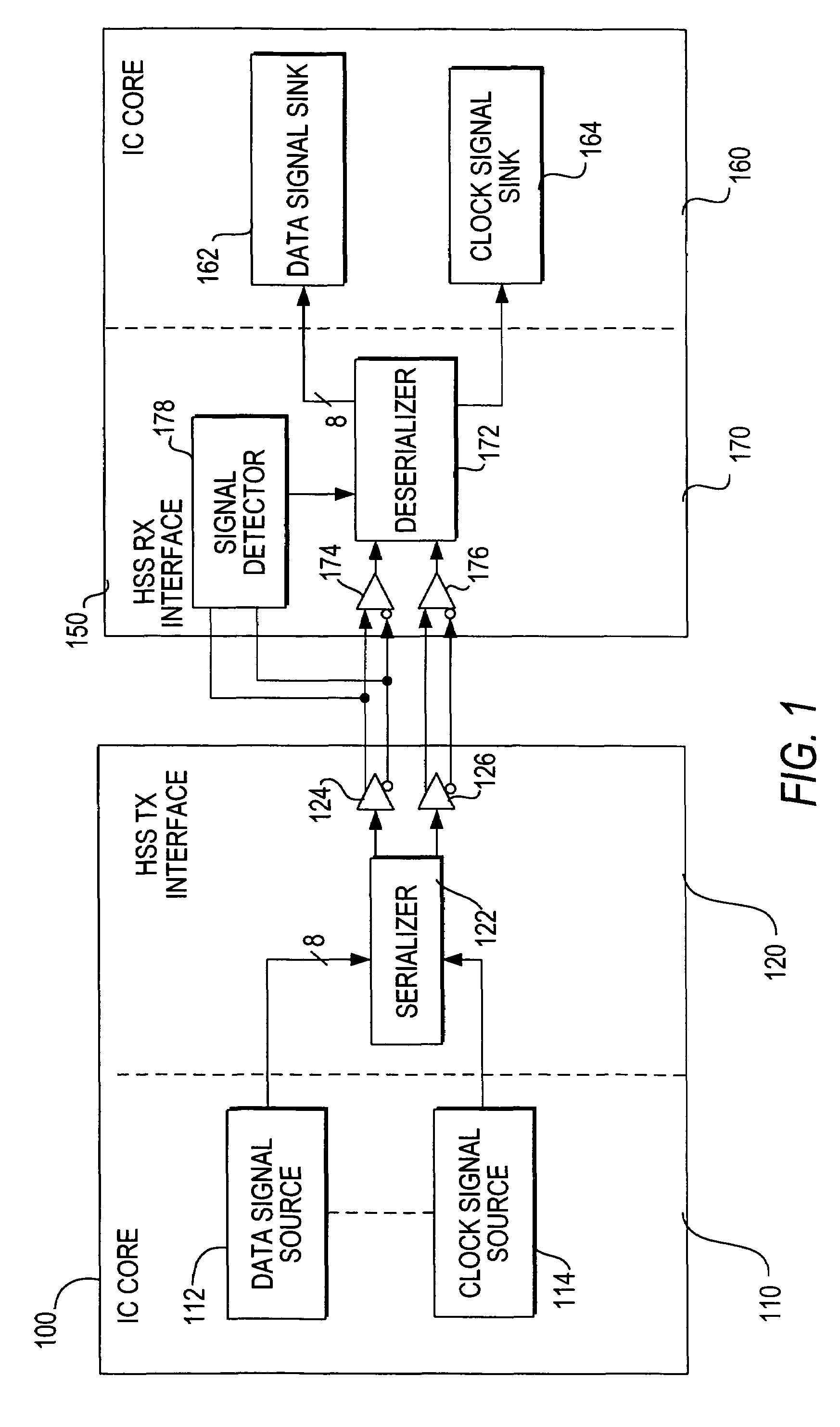
[0020]Two integrated circuit (“IC”) chips 100 and 150 that communicate via a high speed serial interface are shown in FIG. 1. Because all elements of transmitting IC 100 have analogous elements in IC 150 that perform the reverse function, corresponding elements are referred to by numbers that differ by 50. Although the interface is shown as occurring between two different ICs, it could also be used for communication within a single IC. Furthermore, the ICs can be of various types, such as programmable logic devices, application-specific integrated circuits, or hybrids of the two.

[0021]IC 100 comprises an IC core 110 and a HSS transmission interface 120. IC core 110 contains data signal source 112 and clock signal source 114. Element 112 generates 8-bit bytes to be ultimately transmitted to IC 150. Element 114 generates a clock signal that is associated with the data signal from element 112. The dotted line connecting data signal source 112 and clock signal source 114 indicates a pre...


PUM


Abstract

Circuitry and methods allow signal detection based entirely on differential voltage pairs. An incoming differential data signal is processed by separate full-wave rectifiers to extract high and low peak voltage envelopes. The rectifiers utilize negative feedback to ensure accurate envelope detection, and can detect peaks regardless of incoming signal polarity. The extracted envelopes are compared to a differential pair of threshold voltages. If the envelope signals have a smaller voltage difference than that of the threshold signals, the final output of the detector indicates that a loss-of-signal condition has occurred. Fully differential operation makes the detector independent of common-mode voltage, and thus more robust.

Description

CROSS-REFERENCE TO RELATED APPLICATION[0001]This application is a division of U.S. patent application Ser. No. 10 / 833,706, filed Apr. 27, 2004 now U.S. Pat. No. 7,157,944, which is hereby incorporated by reference herein in its entirety.BACKGROUND OF THE INVENTION[0002]High speed serial (“HSS”) data communication is constantly increasing in importance. It permits more efficient pin usage and power consumption than traditional parallel data communication, while preserving or increasing available bandwidth.[0003]The extremely fast data rate associated with HSS communication makes the verification of signal integrity an important concern. The receiving end of a link must know when the sending end has ceased data transmission, either intentionally or as a result of system failure or signal degradation. Thus, effective signal detection is necessary for reliable HSS communication.[0004]One simple solution would be to introduce an extra signal that runs parallel to the transmitted data. Th...

Claims


Application Information

Patent Timeline
Patent Type & Authority Patents(United States)
IPC IPC(8): G01R19/00H03K5/22
CPCG01R19/04G01R19/10H04L25/0272G01R19/16566
Inventor WANG, SHOUJUNBEREZA, BILLKWASNIEWSKI, TADBAIG, MASHKOORMEI, HAITAO
Owner ALTERA CORP
Why Eureka
Try Eureka