Superconducting magnet apparatus

a superconducting magnet and apparatus technology, applied in the direction of superconducting magnets/coils, permanent superconductor devices, magnetic bodies, etc., can solve the problems of difficult to reduce contact resistance sufficiently, increase the load of an external refrigerator which cools the inside of the superconducting magnet apparatus, and take time to cool or heat between on-state, etc., to achieve the effect of reducing the load of the refrigerator that cools the current lead, reducing heat generation, and absorbing

Inactive Publication Date: 2007-05-29
CENTRAL JAPAN RAILWAY COMPANY
View PDF4 Cites 11 Cited by
  • Summary
  • Abstract
  • Description
  • Claims
  • Application Information

AI Technical Summary

Benefits of technology

[0021]According to the above configuration, when the switch is turned on to switch into a persistent current mode in an excited state, it takes a certain amount of time to complete the switching process since the thermal superconducting switch uses the thermal phenomena, but the output current of the external power source can be attenuated (shut off) immediately by the instant switching of the mechanical switch. As a consequence, since the current-carrying time of the current lead is shortened and the heat generation is reduced, the load of the refrigerator that cools the current lead can be reduced.
[0032]According to the above constitution, by using effectively the magnetic field that superconducting coil generates and by a simple constitution, the mechanical switch can be switched.

Problems solved by technology

However, conventional superconducting magnet apparatuses have the following problems, when each superconducting switch is adopted in the excitation circuit.
In the case of using a thermal superconducting switch alone, there is a disadvantage that it takes time to cool or to heat between ON-state (superconducting state) and OFF-state (normal conduction state).
As a consequence, during excitation when the superconducting magnet apparatus is switched into the persistent current mode, the energized time of the current lead becomes longer and the Joule heat increases, thus causing a problem of an increase in the load of an external refrigerator which cools inside of the superconducting magnet apparatus.
In the case of employing a mechanical superconducting switch alone, it is possible to turn it on and off instantly, but it is difficult to decrease contact resistance sufficiently in an ON-state, so the contact resistance causes problems such as current decay and heat generation when the switch is connected to the superconducting coil.
Furthermore, there is a disadvantage in that considerable invasion heat from the drive mechanism that drives the contact in a contact or non-contact state increases heat load of the superconducting coil.
As shown in FIG. 5, in the case of connecting a thermal superconducting switch and a mechanical superconducting switch in parallel, as in the case of employing a mechanical superconducting switch alone, there is the same disadvantage that invasion heat from the drive mechanism that drives the contact increases the heat load of the superconducting coil.
There also is a problem that the contact resistance of the mechanical superconducting switch causes heat generation until the thermal superconducting switch has completed switching when turned on.

Method used


Image

  • Superconducting magnet apparatus
  • Superconducting magnet apparatus
  • Superconducting magnet apparatus

Examples


first embodiment

[0044

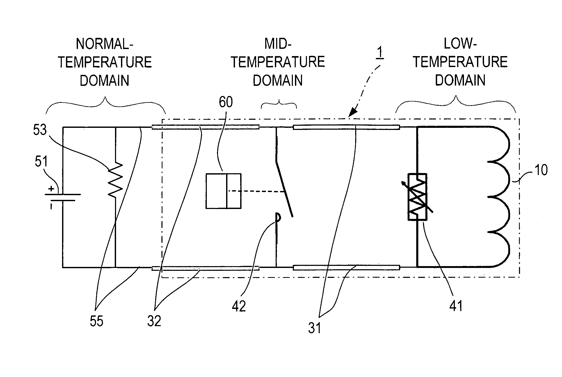
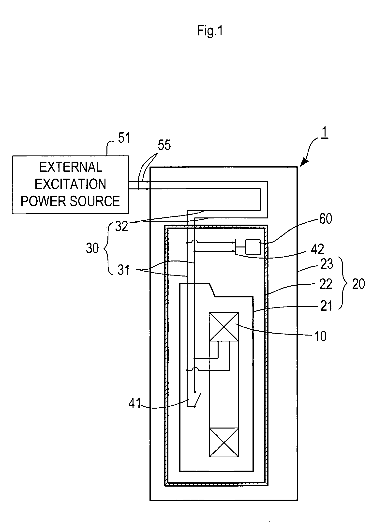
[0045]The present embodiment describes a superconducting magnet apparatus for Maglev according to the present invention. FIG. 1 is an explanatory view (cross sectional view) showing a schematic constitution of the superconducting magnet apparatus. FIG. 2 is an explanatory view showing a schematic electric constitution of the superconducting magnet apparatus.

[0046]As shown in FIG. 1, the superconducting magnet apparatus 1 of the present embodiment comprises a vacuum container 20 housing a superconducting coil 10 inside the vacuum container 20, and a current lead 30 placed in the vacuum container 20 for supplying an electric current to the superconducting coil 10 from an external excitation power source 51.

[0047]The vacuum container 20 comprises an inner tank 21 in which a low-temperature domain is formed and the superconducting coil 10 is placed, a heat shield 22 covering the inner tank 21 in which a mid-temperature domain whose temperature is higher than the low-temperature dom...

second embodiment

[0064

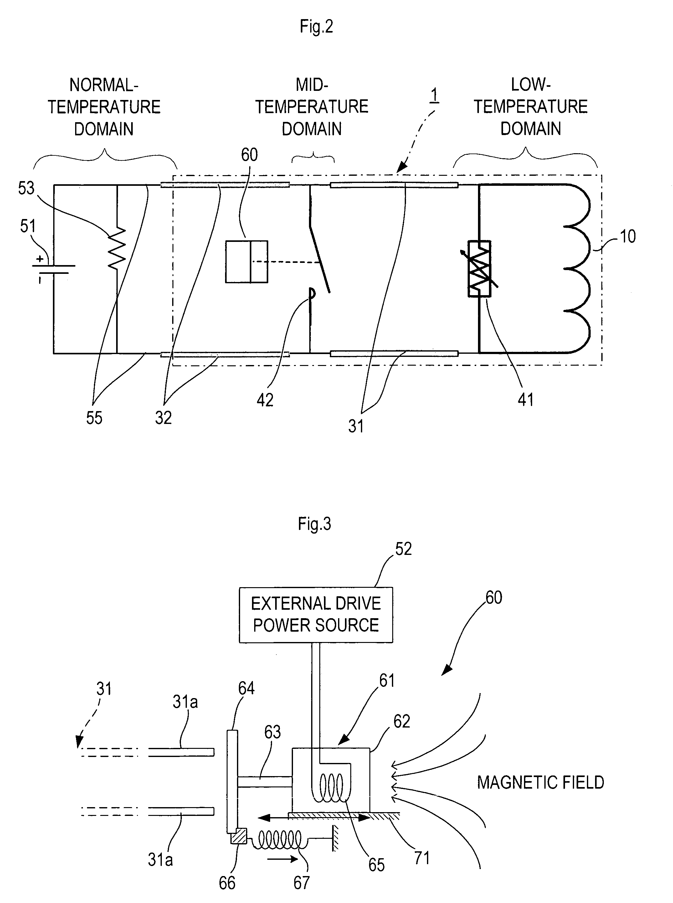
[0065]In the above first embodiment, the driving mechanism 60 utilizing the normal conducting solenoid 65 is employed as a driving mechanism to turn on and off the mechanical switch 42. The present embodiment employs a driving mechanism that is different from the first embodiment. FIG. 4 is a schematic view of the driving mechanism, which corresponds to FIG. 3 in the first embodiment. The basic constitution of the present superconducting magnet apparatus, the manner of supplying electric power, etc. are substantially identical in principle with those in the first embodiment. Therefore, the identical components are numbered the same and an explanation thereof is not repeated.

[0066]As shown in FIG. 4, a driving mechanism 80 in this embodiment comprises a slide mechanism 81 that performs sliding movement by applying a given voltage to an ultrasonic motor from the external drive power source 52 to drive the same.

[0067]The slide mechanism 81 comprises an ultrasonic motor 82 includin...


PUM

PropertyMeasurementUnit
temperatureaaaaaaaaaa

Abstract

This invention provides a superconducting magnet apparatus capable of preventing or restraining the heat invading into the apparatus and reducing the refrigeration load of an external refrigerator, at the time of changeover of a switch in transiting to a persistent current mode, and capable of quick changeover operation. In the superconducting magnet apparatus of the present invention (1), in transiting to a persistent current mode, a thermal superconducting switch (41) placed in a low-temperature domain and a mechanical switch (42) placed in a mid-temperature domain are turned on. Since the mechanical switch (42) is placed in the mid-temperature domain, even if a heat load is generated through the drive mechanism (60), it is not necessary to cool the mechanical switch to an extremely low temperature. In short, heat generated at the contact point of the mechanical switch (42) and heat invasion through the drive mechanism (60) are applied not to the low-temperature domain, but to the mid-temperature domain, so that an external refrigerator can easily absorb the heat load and the capacity of the refrigerator can be reduced.

Description

TECHNICAL FIELD[0001]This invention relates to a superconducting magnet apparatus that switches itself into a persistent current mode by changeover of switches after excitation.BACKGROUND ART[0002]Along with improvements in performance of the superconducting wires and advances in coil manufacturing techniques using such wires, as well as technical developments in related apparatuses such as heat-insulating containers and refrigerators, various types of superconducting magnets and application apparatuses employing such magnets have been created. Among these, there is a type which is operated in a persistent current mode. Superconducting magnet apparatuses for magnetic resonance imaging systems (MRI) and for magnetically levitated vehicles (Maglev) are examples of this type which have already been put into practical use. These superconducting magnet apparatuses supply an electric current from an external excitation power source to a coil that is cooled to an extremely low temperature....

Claims


Application Information

Patent Timeline
Patent Type & Authority Patents(United States)
IPC IPC(8): H01L39/02H01L39/14H01F6/04H01L39/20
CPCH01F6/04Y10S505/879H10N60/20
Inventor NEMOTO, KAORUIGARASHI, MOTOHIRO
Owner CENTRAL JAPAN RAILWAY COMPANY
Why Eureka
Try Eureka