Physical quantity sensing element having improved structure suitable for electrical connection and method of fabricating same

a sensing element and electrical connection technology, applied in the field of physical quantity sensors, can solve the problems of inability to provide a correct electrical signal, difficult to make electrical connection of the sensing element with external devices and circuits, for example, electrical terminals and wire bonding, etc., to achieve the effect of convenient electrical connection of the sensing element, improved structure suitable for electrical connection, and easy fabrication

Inactive Publication Date: 2007-05-29
DENSO CORP
View PDF16 Cites 25 Cited by
  • Summary
  • Abstract
  • Description
  • Claims
  • Application Information

AI Technical Summary

Benefits of technology

[0016]In such a structure, means for outputting electrical signals, such as electrodes and terminals, can be provided on the second area of the surface of the sensing layer which is free from application of the physical quantity to the sensing element. As a consequence, the electrical signal outputting means can be prevented from being damaged due to application of the physical quantity, while facilitating the electrical connection of the sensing element with external devices and circuits.
[0048]The improved structure of the physical quantity sensing element according to the invention facilitates electrical connection of the sensing element with external devices and circuits, while preventing the electric signal outputting means provided in the sensing element from being damaged due to application of large physical quantities.

Problems solved by technology

With such a structure, the electrode layers may become damaged when a large physical quantity is applied to the sensing element, so that the sensing element cannot provide a correct electrical signal representative of the applied physical quantity.
However, with such an arrangement of electrodes, it becomes difficult to make electric connection of the sensing element with external devices and circuits by means of, for example, electrical terminals and wire bonding.

Method used


Image

  • Physical quantity sensing element having improved structure suitable for electrical connection and method of fabricating same
  • Physical quantity sensing element having improved structure suitable for electrical connection and method of fabricating same
  • Physical quantity sensing element having improved structure suitable for electrical connection and method of fabricating same

Examples


first embodiment

[First Embodiment]

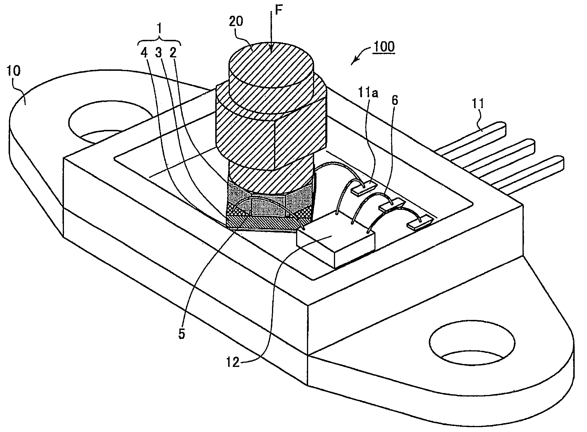
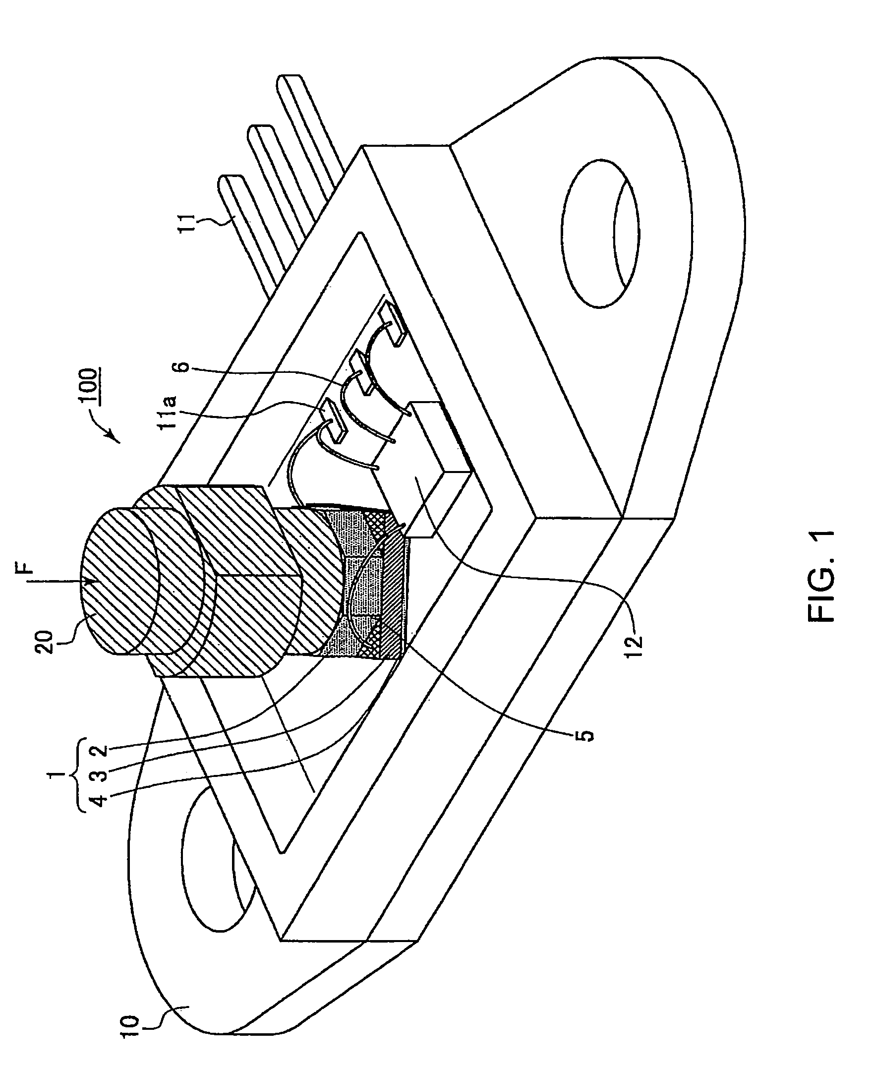
[0062]FIG. 1 shows an overall structure of a physical quantity sensor 100 that includes a physical quantity sensing element 1 according to the present embodiment.

[0063]The physical quantity F to be sensed is, for example, a load; it is applied to the physical quantity sensor 100 in the direction indicated by the straight-line arrow.

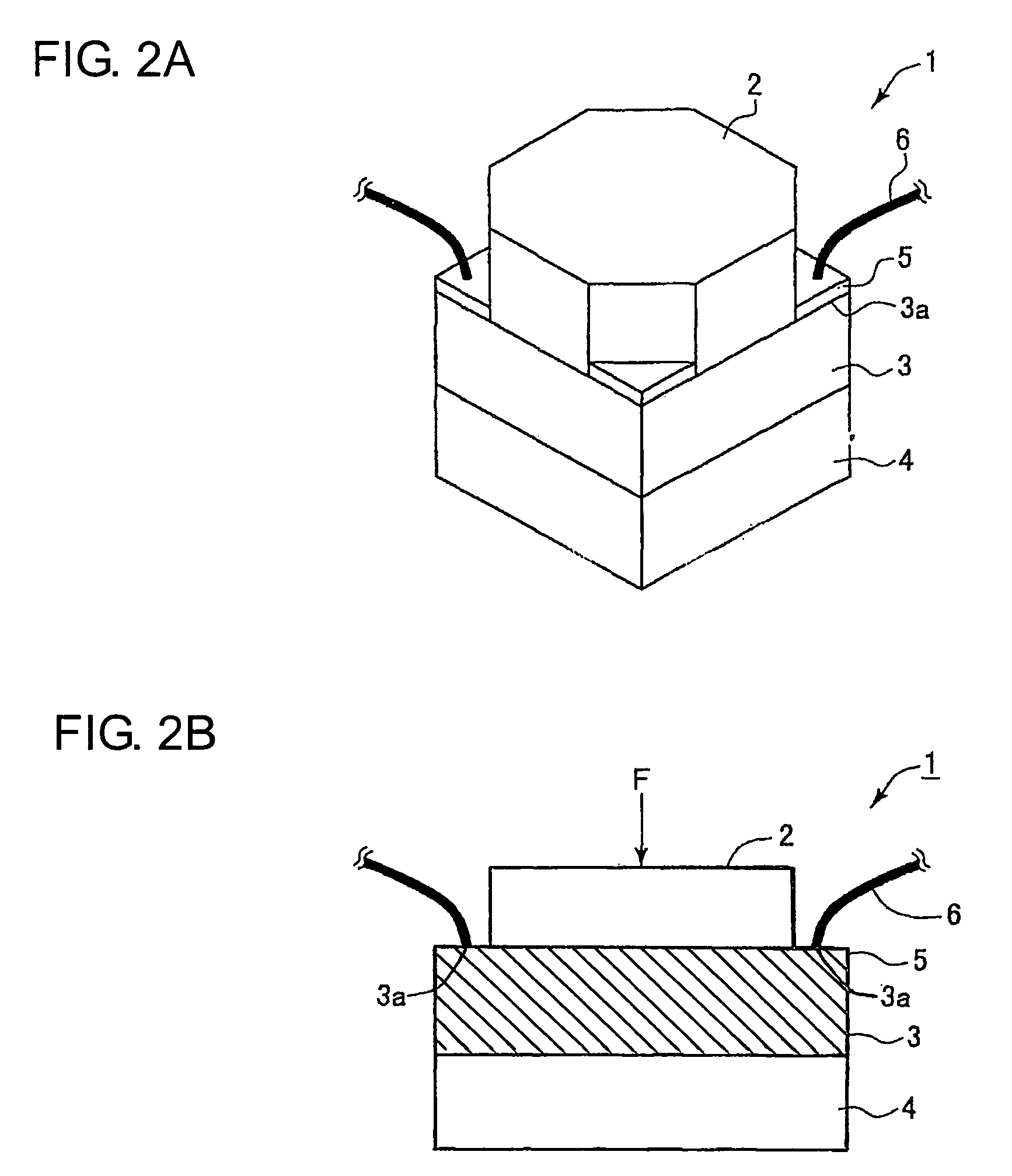
[0064]The physical quantity sensing element 1 includes, as shown in FIG. 1, a first insulating layer 2, a sensing layer 3, and a second insulating layer 4, all of which are stacked in the application direction of the physical quantity F.

[0065]On the first insulating layer 2, there is provided a joint 20 for joining the physical quantity sensor 100 to a physical quantity applying device (not shown), so that the physical quantity F is to be applied through the first insulating layer 2 to the sensing layer 3. A case 10, which is made of ceramic, supports the sensing element 1 against application of the physical quantity F.

[0066]The case 10 ...

second embodiment

[Second Embodiment]

[0101]FIG. 5 shows a physical quantity sensing element 1′ according to the second embodiment of the present invention.

[0102]The physical quantity sensing element 100 has a structure almost identical to that of the physical quantity sensing element 1 according to the previous embodiment. Accordingly, only the difference between the structures of the physical quantity sensing elements 1 and 1′ will be described below.

[0103]As described previously, in the physical quantity sensing element 1, the surface of the sensing layer 3 includes a first area that is completely covered with the first insulating layer 2 and a second area that consists of the electrical connection areas 3a. The first and the second area together constitute the major face of the sensing layer 3 that is a unitary flat surface.

[0104]In comparison, in the physical quantity sensing element 1′, the first and the second areas lie on different planes. More specifically, as shown in FIG. 5, the major face ...

third embodiment

[Third Embodiment]

[0108]FIG. 6 illustrates a method of fabricating a physical quantity sensing element of the invention according to the present embodiment.

[0109]In the figure, there is shown the physical quantity sensing element 1 of the first embodiment of the invention. However, the fabrication method of the present embodiment should not be limited to fabrication of the specific physical quantity sensing element 1; it can also be applicable to fabrication of any other physical quantity sensing elements according to the invention.

[0110]Fabrication of the physical quantity sensing element 1 has been conducted by the following steps.

[0111]In Step 1, powders of a piezoresistive material of La0.62Sr0.38MnO3 and a ceramic of 12 wt % CeO2 added ZrO2 for constituting the matrix were blended at a given ratio, for example, of 3:7 to provide a blended powder for forming the sensing layer 3. The blended powder was then mixed and crushed for four hours in a pulverizing mill, for example a bal...


PUM

PropertyMeasurementUnit
angleaaaaaaaaaa
thicknessaaaaaaaaaa
thicknessaaaaaaaaaa

Abstract

A physical quantity sensing element according to the invention includes an insulating layer and a sensing layer. The sensing layer is configured to generate an electrical signal as a function of a physical quantity applied thereto and has a surface that includes a first and a second area. The first area is completely covered with the insulating layer so that the physical quantity is to be applied to both the insulating layer and the sensing layer through the first area; the second area is exposed to an application direction of the physical quantity without being covered with the insulating layer and being subject to application of the physical quantity. With such a structure, easy and reliable electrical connection of the physical quantity sensing element with external devices and circuits is ensured. In addition, several practical methods of fabricating the physical quantity sensing element according to the invention are also provided.

Description

CROSS-REFERENCE TO RELATED APPLICATION[0001]This application claims priority from Japanese Patent Application No. 2003-431012, filed on Dec. 25, 2003, the content of which is hereby incorporated by reference into this application.BACKGROUND OF THE INVENTION[0002]1. Technical Field of the Invention[0003]The present invention relates generally to physical quantity sensors for sensing physical quantities such as force, pressure, torque, velocity, acceleration, impact strength, weight, mass, degree of vacuum, turning effort, vibration, and noise. More particularly, the invention relates to an improved structure of a physical quantity sensing element which ensures easy and reliable electrical connection of the sensing element with external devices and circuits.[0004]2. Description of the Related Art[0005]Physical quantity sensors, such as load sensors making use of piezoresistive materials and pressure sensors employing pressure-sensitive elements, have been widely used. The piezoresisti...

Claims


Application Information

Patent Timeline
Patent Type & Authority Patents(United States)
IPC IPC(8): H01C10/10G01D9/00G01L1/26G01D21/00G01G3/12G01J1/34G01L1/18G01L9/06H01C17/065H01J3/14
CPCG01G3/12G01L1/18H01C17/065
Inventor MORIKAWA, KENJI
Owner DENSO CORP
Why Eureka
Try Eureka