
Low noise multi-wavelength light source and wavelength division multiplexing system using same

a multi-wavelength light source and wavelength division multiplexing technology, applied in multiplex communication, semiconductor lasers, instruments, etc., can solve the problems of increasing the size of the wavelength division multiplexed optical communication system, increasing the manufacturing cost, and not only the single-wavelength light source must be provided to the system, so as to achieve low relative noise and low manufacturing cost

Inactive Publication Date: 2007-05-29
SAMSUNG ELECTRONICS CO LTD
View PDF37 Cites 20 Cited by
  • Summary
  • Abstract
  • Description
  • Claims
  • Application Information

AI Technical Summary

Benefits of technology

[0013]Accordingly, the present invention provides a multi-wavelength light source that has both a low relative intensity of noise and a low manufacturing cost.
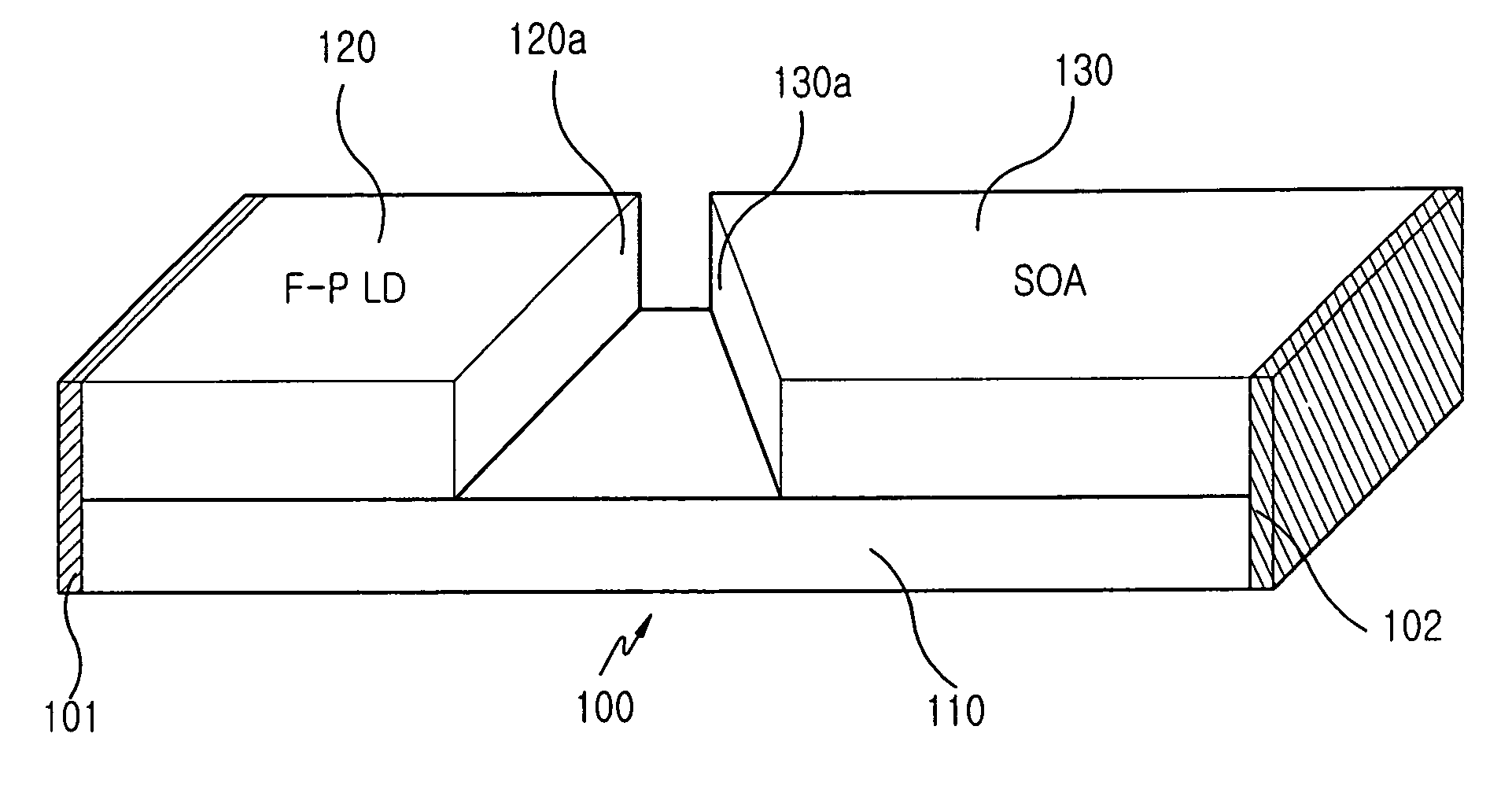
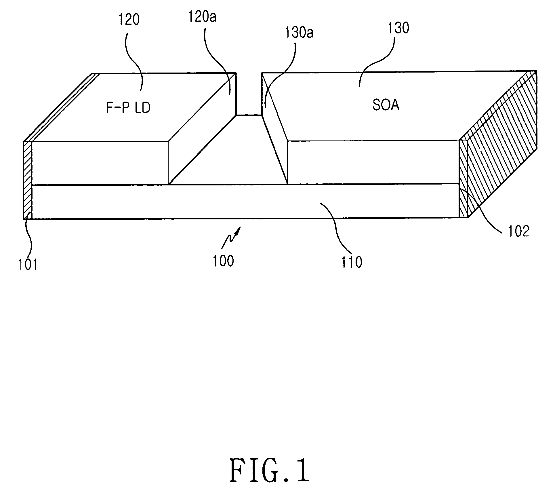
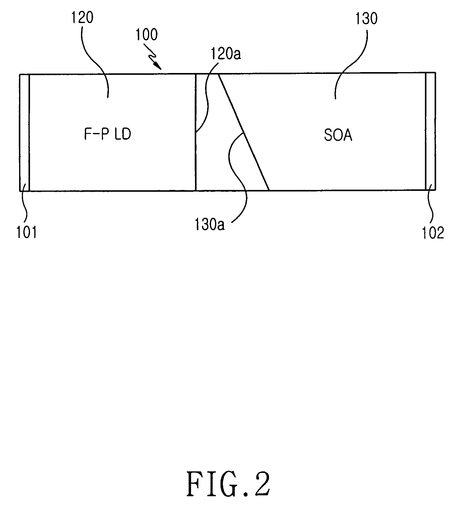
[0014]According to a first aspect of the present invention, there is provided a multi-wavelength light source comprising: a substrate, a fabry-perot laser laminated on the substrate, and driven by driving current below threshold current, thereby generating multi-wavelength light including a plurality of peaks whose wavelengths and spacing are identical to these of WDM channels, and a semiconductor optical amplifier laminated on the substrate in such a manner that a slant surface of the semiconductor optical amplifier is opposed to a side surface of the fabry-perot laser, thereby amplifying the multi-wavelength light outputted from the fabry-perot laser, wherein the semiconductor optical amplifier is operated in a gain saturation state, thereby reducing the relative intensity noise of channels of the multi-wavelength light and simultaneously amplifying the multi-wavelength light.

Problems solved by technology

However, one drawback of using single-wavelength light sources is that a plurality of single-wavelength light sources must be provided to the system in order to correspond respectively to the number of transmitted channels.
This one to one correspondence increases not only the size of the wavelength division multiplexed optical communication system increases, but also the manufacturing costs.
However, the multi-wavelength light sources have the problem that they output incoherent light.
Therefore, in comparison with the single-wavelength light source, the multi-wavelength light sources are disadvantageous in a long-distance transmission.
However, the fabry-perot laser does not solve all the above-mentioned problems, particularly when used in multi-wavelength light source.
The multiple channels output from the laser are subject to power fluctuation that commonly occurs, thereby increasing relative intensity noise.

Method used


Image

  • Low noise multi-wavelength light source and wavelength division multiplexing system using same
  • Low noise multi-wavelength light source and wavelength division multiplexing system using same
  • Low noise multi-wavelength light source and wavelength division multiplexing system using same

Examples


first embodiment

[0028]FIG. 3 is a graph of a gain curve showing correlation between the power of multi-wavelength lights input to the SOA shown in FIG. 1, and power of the multi-wavelength lights amplified by the SOA. Further, FIG. 4 shows the power of the multi-wavelength lights inputted to the SOA shown in FIG. 1, and FIG. 5 shows the power of the multi-wavelength lights amplified by the SOA shown in FIG. 1. Hereinafter, an operation characteristic of the multi-wavelength light source shown in FIG. 1 according to the present invention will be described with reference to FIGS. 3 to 5.

[0029]The gain curve of the SOA shown in FIG. 3 shows variation of the power of the multi-wavelength lights 310, 320 input to and amplified by the SOA versus the output values 311, 321, respectively. The graph has a linear region and a gain saturation region. In the linear region, as the power of the multi-wavelength lights input to the SOA increases, the power of the amplified multi-wavelength light output gradually ...

second embodiment

[0033]FIG. 6 is a block diagram showing a wavelength division multiplexed communication system including a multi-wavelength light source according to the present invention. The wavelength division multiplexed communication system includes a central office 200 outputting multi-wavelength light, a remote node 230 connected to the central office 200 through an optical fiber, and a plurality of subscribers 240-1 to 240-n connected to the remote node 230.

[0034]The central office 200 includes a light source section 210 for generating multi-wavelength light comprising the fabry-perot laser 211 and the SOA 212, wherein the output of the light source section 211 is demultiplexed by, a demultiplexer 220, a plurality of modulators 201-1 to 201-n for modulating the respective multiplexed signals individually, a plurality of photodetectors 203-1 to 203-n for detecting upstream channels sent by subscribers via the remote node 230 and demultiplexed by a first Mux / Demux 221 and a plurality of wavel...


PUM

PropertyMeasurementUnit
multi-wavelengthaaaaaaaaaa
wavelengthsaaaaaaaaaa
band gapaaaaaaaaaa

Abstract

A multi-wavelength light source includes a substrate, a fabry-perot laser laminated on the substrate that is operated by driving current below a predetermined threshold current to generate multi-wavelength light including a plurality of peaks whose wavelengths and spacing are identical to these of WDM channels. A semiconductor optical amplifier (SOA) is laminated on the substrate in an arrangement such that a slant surface of the SOA is opposed to a side surface of the fabry-perot laser, which serves to thereby amplify the multi-wavelength light output from the fabry-perot laser. The semiconductor optical amplifier is driven in a gain saturation state to reduce the relative intensity of noise in the channels of the multi-wavelength light that are simultaneously amplified.

Description

CLAIM OF PRIORITY[0001]This application claims priority to an application entitled “Multi-wavelength light source and wavelength division multiplexing system using the same,” filed in the Korean Intellectual Property Office on Aug. 29, 2003 and assigned Serial No. 2003-60191, the contents of which are hereby incorporated by reference.BACKGROUND OF THE INVENTION[0002]1. Field of the Invention[0003]The present invention relates to light sources that are used for optical communications. More particularly, the present invention relates to a multi-wavelength light source which can output multi-wavelength light in a multiplex system that includes a plurality of channels having differing wavelengths.[0004]2. Description of the Related Art[0005]In wavelength division multiplexed optical communication systems, a plurality of channels having different wavelengths are multiplexed into as a composite optical signal that is transmitted across a transmission medium. The multiplexed optical signal...

Claims


Application Information

Patent Timeline
Patent Type & Authority Patents(United States)
IPC IPC(8): H01S5/50H04J14/02G02B6/36G02F1/39H01S5/026H01S5/028H01S5/10H01S5/14H04B10/2507H04J14/00
CPCH01S5/0265H01S5/14H01S5/028H01S5/06812H01S5/1092H01S5/1085H04J14/02
Inventor SHIN, HYUN-CHEOLLEE, JEONG-SEOKHWANG, SEONG-TAEKJUNG, DAE-KWANG
Owner SAMSUNG ELECTRONICS CO LTD
Learn More