Compact fast catadioptric imager

a catadioptric imager, fast technology, applied in the field of catadioptric imagers, can solve the problems of limited compactness, achieve the effect of maintaining telecentricity in image space, limiting compactness, and minimizing the obscuration of optical rays

Active Publication Date: 2007-05-29
WAVEFRONT RES
View PDF7 Cites 43 Cited by
  • Summary
  • Abstract
  • Description
  • Claims
  • Application Information

AI Technical Summary

Benefits of technology

[0019]Conventional infrared imaging spectrometers typically use three-mirror anastigmats (TMAS) as imaging fore-optics, which are limited in their compactness due to the inherent obscuration effect of mirrors. In this invention, an improved catadioptric design form allows for the imaging lens to be folded upon itself, and the elements are arranged such that the obscuration of the optical rays are substantially minimized while maintaining telecentricity in image space without vignetting. This provides several advantages including, but not limited to, a high optical throughput and an improved overall compactness of the system.

Problems solved by technology

Conventional infrared imaging spectrometers typically use three-mirror anastigmats (TMAS) as imaging fore-optics, which are limited in their compactness due to the inherent obscuration effect of mirrors.

Method used


Image

  • Compact fast catadioptric imager
  • Compact fast catadioptric imager
  • Compact fast catadioptric imager

Examples


Embodiment Construction

[0024]An optically fast, telecentric catadioptric imager is disclosed hereinbelow.

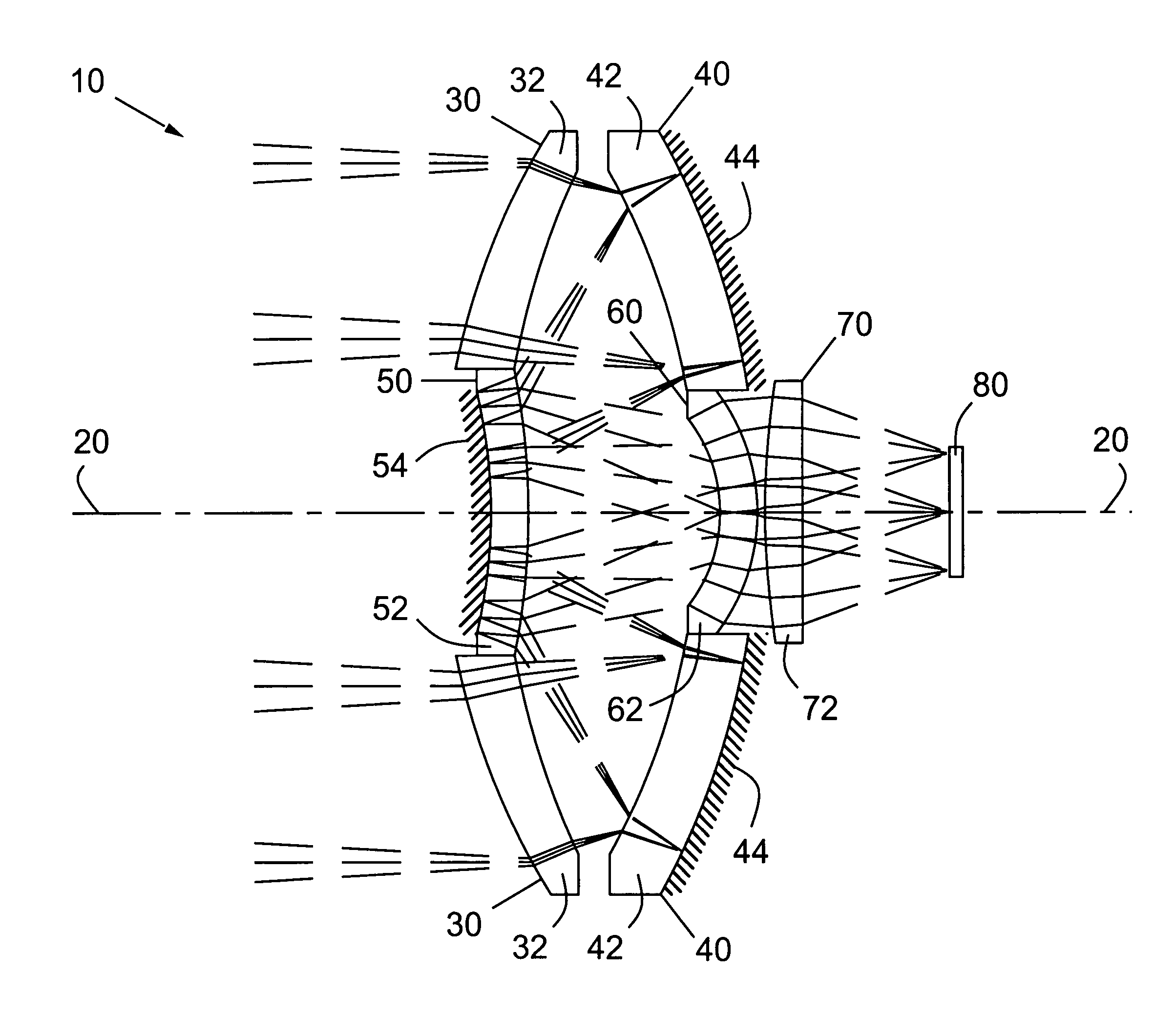
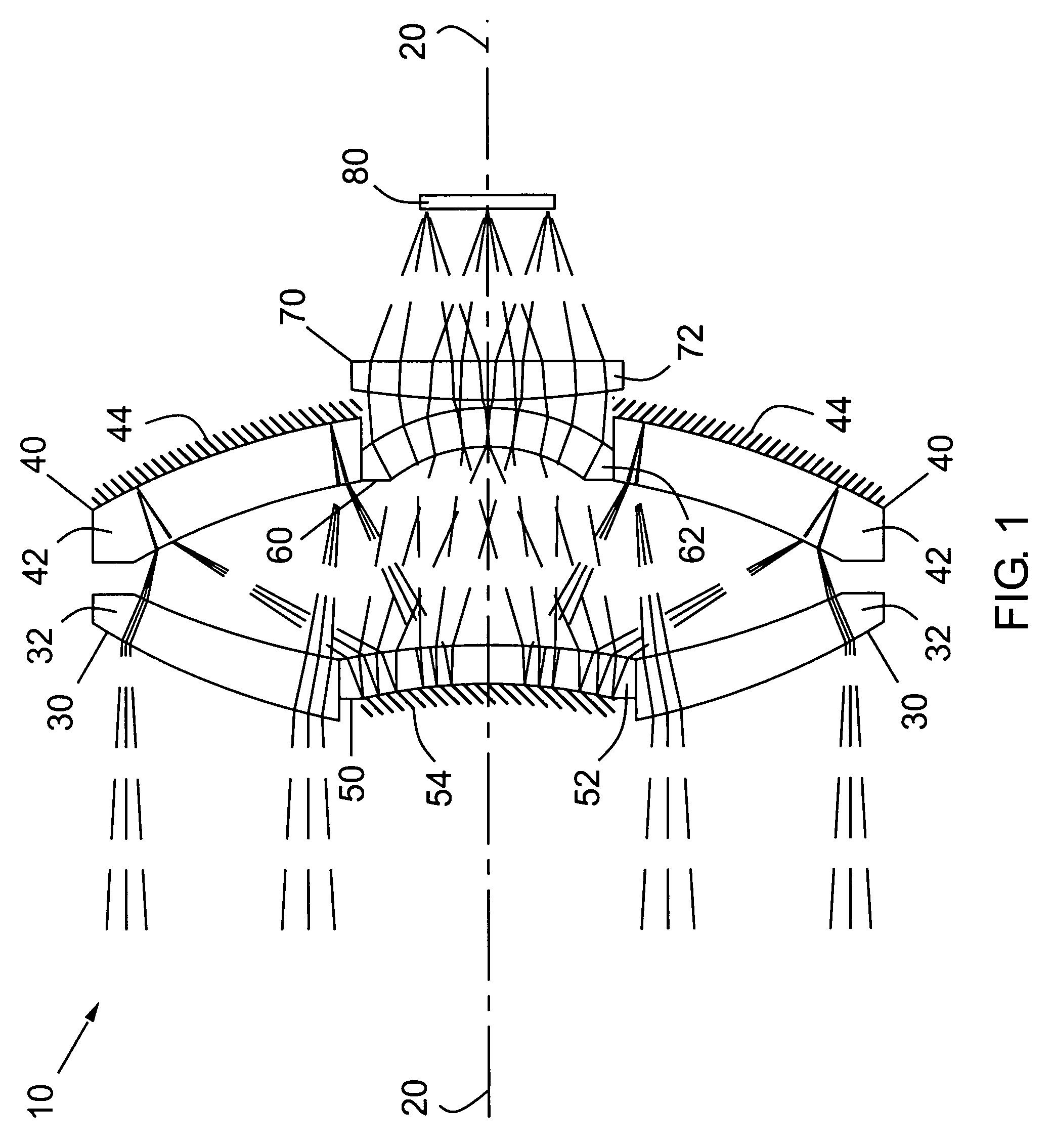
[0025]Reference is made to FIG. 1, which is a schematic sectional view of an embodiment of this invention 10, taken along the optical axis 20, the optical prescription for which is given in Table 1. In the operation of this embodiment, electromagnetic radiation, typically in the ultraviolet, visible, and / or infrared bands, hereinafter referred to generally as light, emitted or reflected by a given object, either real or virtual, hereinafter also referred to as a source, is incident upon a first, or hereinafter termed “corrector”, group of optical elements 30. This corrector element group is similar to that of the Bouwers and Maksutov imaging systems, and is comprised of a refractive element or combination of refractive elements, in this embodiment consisting of element 32, having a combined positive or convergent optical power. A portion of the light that is transmitted by the corrector group 30 is nex...


PUM


Abstract

A compact, optically fast catadioptric imager. In one embodiment, the catadioptric imager of this invention includes a first group of optical elements optically disposed to receive electromagnetic radiation from an object and having positive optical power, a second group of optical elements, optically disposed between the first group of optical elements and an image plane, having at least one optical surface and having positive optical power, a third group of optical elements, optically disposed between the object and the second group of optical elements, having at least one optical surface and having negative optical power, a fourth group of optical elements substantially centered along an optical axis of said second group of optical elements and having negative optical power, and a fifth group of optical elements having positive optical power.

Description

BACKGROUND OF THE INVENTION[0001]This invention relates generally to catadioptric imagers, and, more particularly, to an optically fast, telecentric catadioptric imager design.[0002]A catadioptric imager is a device comprised of a combination of both refractive and reflective surfaces that is commonly used to image light emitted or reflected by a given object or scene onto a focal plane where it can be readily observed or recorded.[0003]As an example of an application that underscores the need for improved catadioptric imager designs, a hyperspectral imager is considered below.[0004]A hyperspectral imager, or imaging spectrometer, is a device that is commonly used to examine the spectral, or wavelength dependent, content of an object or scene. These devices are typically comprised of an imaging fore-optic system that images light emitted or reflected by a given object or scene onto a slit element that transmits a single line portion from the image of the object or scene. This slit t...

Claims


Application Information

Patent Timeline
Patent Type & Authority Patents(United States)
IPC IPC(8): G02B13/14G02B13/22G02B17/00
CPCG02B17/0808
Inventor MITCHELL, THOMAS A.
Owner WAVEFRONT RES
Why Eureka
Try Eureka