Pulse width modulator and pulse width modulation method

a pulse width and modulator technology, applied in pulse conversion, instruments, pulse techniques, etc., can solve the problems of requiring many computation steps, causing distortion in reproduced sound, and difficult to provide a high-quality reproduction of sound, so as to reduce nonlinear distortion and reduce nonlinear distortion

Inactive Publication Date: 2007-05-29
PIONEER CORP
View PDF4 Cites 14 Cited by
  • Summary
  • Abstract
  • Description
  • Claims
  • Application Information

AI Technical Summary

Benefits of technology

[0038]The pulse width modulator and the pulse width modulation method perform interpolation processing in accordance with a pulse code modulated data train, thereby producing a PWM signal which is close to a PWM signal generated through the NPWM (Natural Sampling PWM) modulation and can reduce nonlinear distortion.
[0039]Furthermore, the pulse width modulator and the pulse width modulation method employ fewer computation steps to perform the interpolation processing without a division operation, thereby producing a PWM signal which can reduce nonlinear distortion.

Problems solved by technology

For this reason, when compared with a PWM signal generated directly from an analog signal by the NPWM (Natural Sampling PWM) modulation, the PWM signal Su obtained by the aforementioned UPWM modulation may contain nonlinear distortion, thereby raising a problem of causing distortion in reproduced sound, for example, upon allowing the aforementioned loudspeaker or the like to sound.
Accordingly, as can be seen from FIG. 7C, even for the same original analog signal X(t), the PWM signal Su provided by the UPWM modulation and the PWM signal SN provided by the NPWM modulation are in the logic “H” or the logic “L” for different lengths of time in each sampling period (1 / fs), thereby causing a problem of making it difficult to provide a high quality reproduction of sound when the aforementioned loudspeaker or the like is allowed to sound in accordance with the PWM signal Su.
However, as shown by the aforementioned equations (3) and (4), the prior art interpolation method required a division operation to determine the coordinates (tp, Xp) at the point in time tp at which the logic state of the PWM signal Su is inverted, thus raising a problem of requiring many computation steps.
In particular, when the PWM signal Su is produced while the aforementioned interpolation processing is performed on a PCM data train sampled at a higher sampling frequency or on a PCM data train to be generated from data containing many bits (many levels of quantization), the aforementioned division operation resulted in many computation steps and thereby required a long time for the PCM to PWM conversion, thus raising a problem of making it difficult to perform signal processing at high speeds.

Method used


Image

  • Pulse width modulator and pulse width modulation method
  • Pulse width modulator and pulse width modulation method
  • Pulse width modulator and pulse width modulation method

Examples


first embodiment

[0050

[0051]A first embodiment of the present invention will be described with reference to FIGS. 1 to 4B.

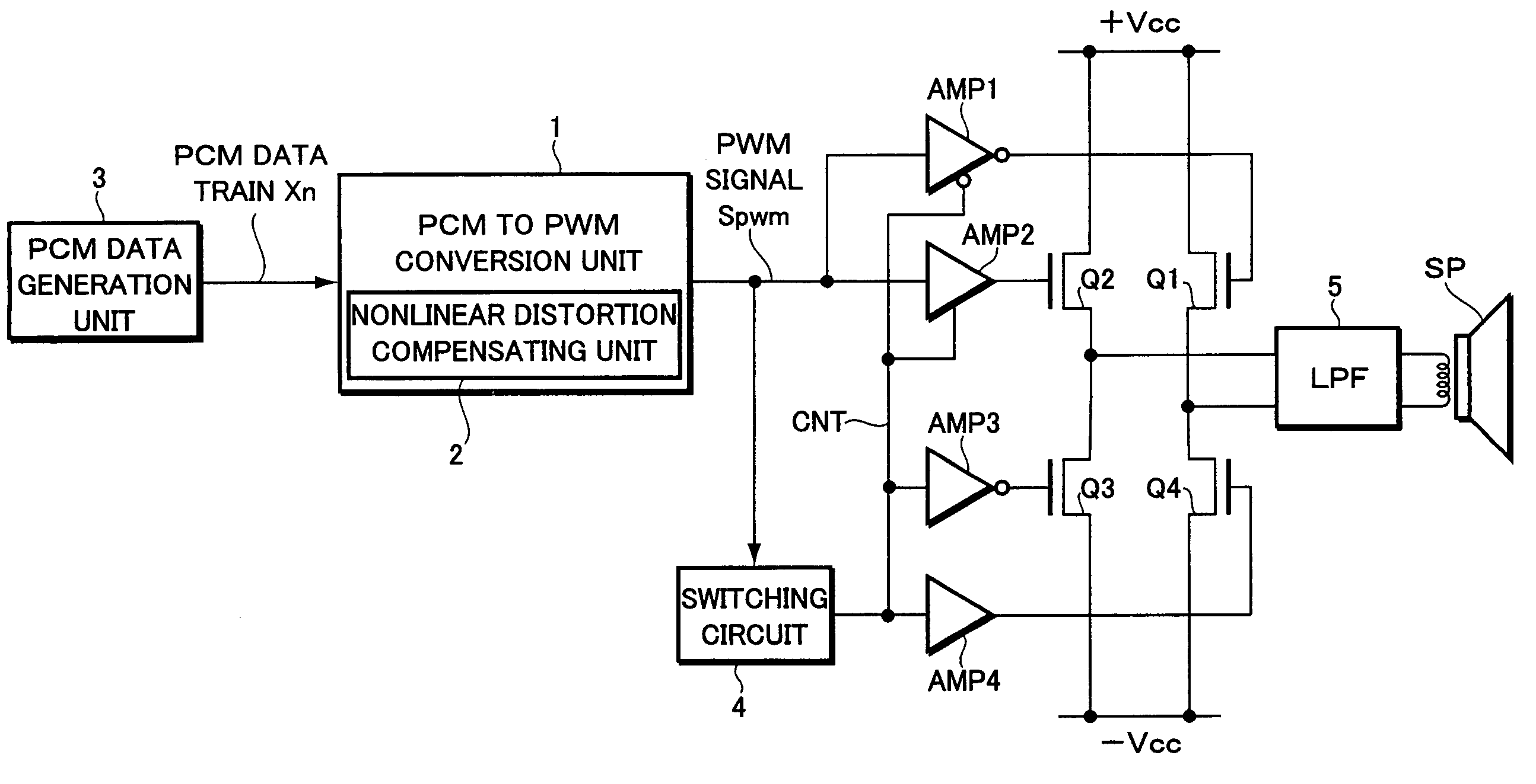
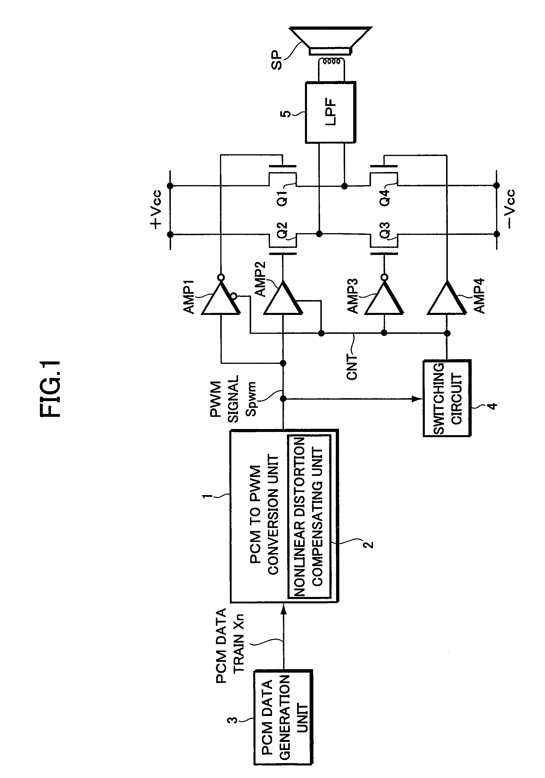
[0052]FIG. 1 is a view showing the configurations of a pulse width modulator according to this embodiment and an exemplary digital amplifier utilizing the pulse width modulator.

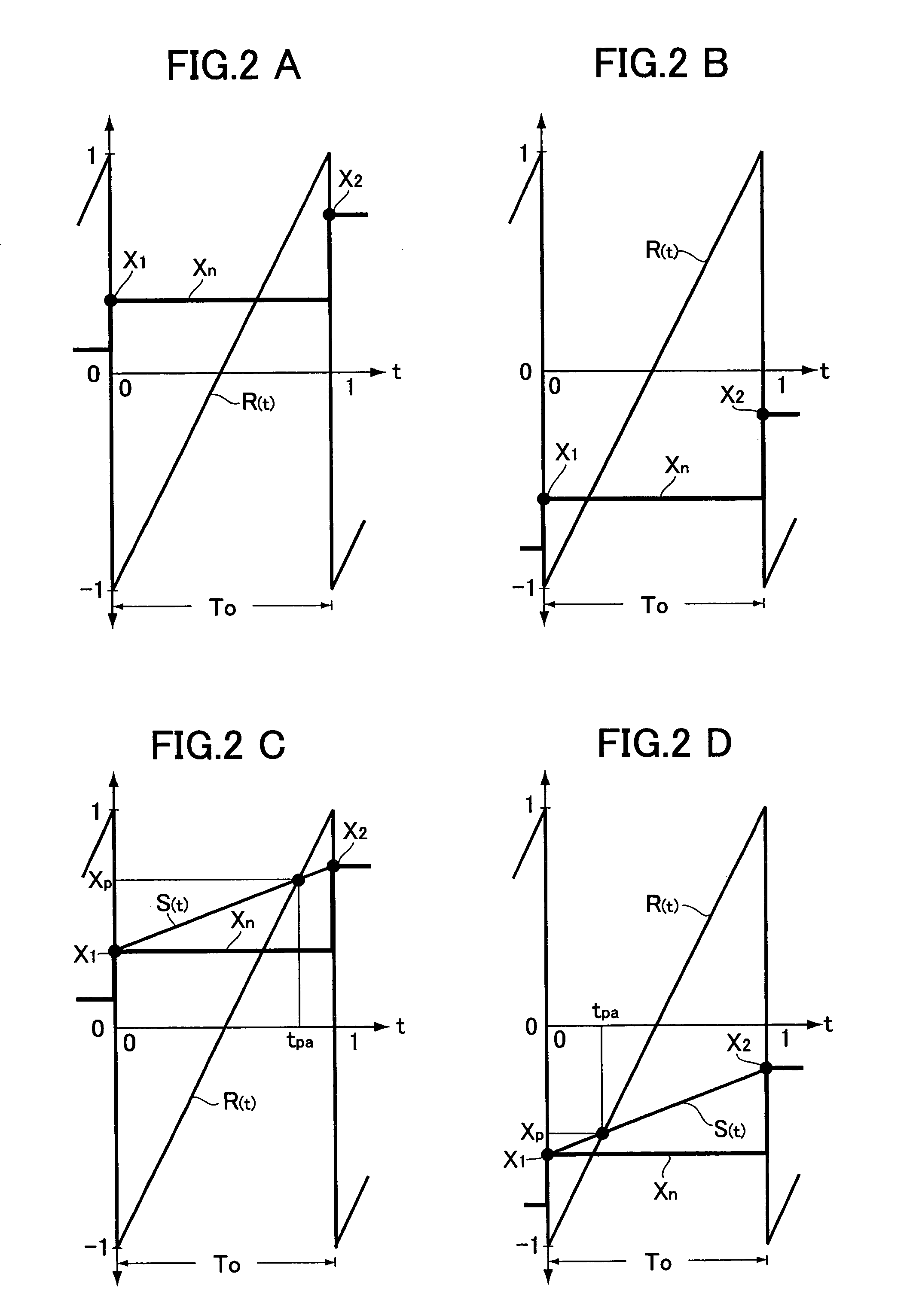
[0053]FIGS. 2A to 4B are views showing the principle of the interpolation processing performed by the pulse width modulator according to this embodiment upon producing a pulse width modulation (PWM) signal.

[0054]First, referring to FIG. 1, explained are the configurations of a pulse width modulator 1 according to this embodiment and an exemplary digital amplifier utilizing the pulse width modulator 1.

[0055]The pulse width modulator 1 includes a PCM to PWM conversion unit in which a PCM data train Xn varying within the range of a positive value and a negative value generated in accordance with a given sampling frequency fs is supplied to allow a sawtooth wave reference signal R(t) varying within the range o...

second embodiment

[0127

[0128]Now, a second embodiment of the present invention will be explained below with reference to FIGS. 5A to 6B.

[0129]This embodiment relates to a pulse width modulator for producing a PWM modulation signal from an oversampled PCM data train.

[0130]FIG. 5A is a view showing the configuration of the pulse width modulator, with the same parts as or the parts corresponding to those of FIG. 1 being indicated by the same symbols.

[0131]Referring to FIG. 5A, this embodiment is different from the first embodiment as follows. That is, a PCM data train Xn of a sampling frequency fs outputted from the PCM data generation unit 3 is oversampled by an oversampling unit 100 at a sampling frequency fov twice as high as the sampling frequency fs, and the pulse width modulator 1 produces and outputs a PWM signal Spwm synchronous with the sampling frequency fs in accordance with the oversampled PCM data train Xn.

[0132]In other words, as shown in FIG. 5B, when a PCM data train Xn of a certain samp...


PUM


Abstract

A pulse width modulator for producing a PWM signal having reduced nonlinear distortion through interpolation processing with fewer computation steps is provided. The computational processing, W={1+α(X2−X1)}{0.25 (X1+X2)}+0.5, is performed in accordance with successive sample values (X1, X2) in a PCM data train to determine a weighting factor (W). The computational processing, Xq=0.5·X0(W2−W)+X1(1−W2)+0.5·X2(W2+W), is performed using the sample values (X1, X2), a sample value (X0) previous to the sample value (X1), and the weighting factor (W) to thereby determine an interpolated sample value (Xq) having an amplitude close to that of an original analog signal (X(t)) generating the PCM data train. A point in time (tq) at which a reference signal (R(t)) takes on the interpolated sample value (Xq) is then determined to produce a PWM signal (Spwm) which is logically inverted at the point in time (tq).

Description

BACKGROUND OF THE INVENTION[0001]The present invention relates to a pulse width modulator and a pulse width modulation method.[0002]The present application claims priority from Japanese Application No.2002-188319, the disclosure of which is incorporated herein by reference.[0003]In the field involving digital signal processing such as the audio video technology, the communication technology, and the computer technology, PCM (pulse code modulated) data trains may be converted into PWM (pulse width modulation) signals for processing.[0004]For example, a digital amplifier is conventionally known which performs a PCM to PWM conversion on a PCM data train, such as speech or music, reproduced such as with a CD (Compact Disc) player or a DVD (Digital Versatile Disc) player, to derive a PWM signal, which is in turn used to control a current supplied to a loudspeaker or the like, thereby providing a sound corresponding to the PWM signal.[0005]In general, such a method as shown in FIG. 7A is ...

Claims


Application Information

Patent Timeline
Patent Type & Authority Patents(United States)
IPC IPC(8): H03K7/08H03F3/217H03M1/82H03F3/38H03M5/08
CPCH03M5/08
Inventor KOMAMURA, MITSUYA
Owner PIONEER CORP
Why Eureka
Try Eureka