

Plate image inspection for printing prepress
a plate image and prepress technology, applied in the field of prepress technology, can solve the problems of time-consuming comparison of data before and after proofing to perform prepress, and achieve the effect of speeding up the plate image inspection
- Summary
- Abstract
- Description
- Claims
- Application Information
AI Technical Summary
Benefits of technology
Problems solved by technology
Method used
Image

Examples
embodiment 1
B2. Embodiment 1 of Plate Image Inspection
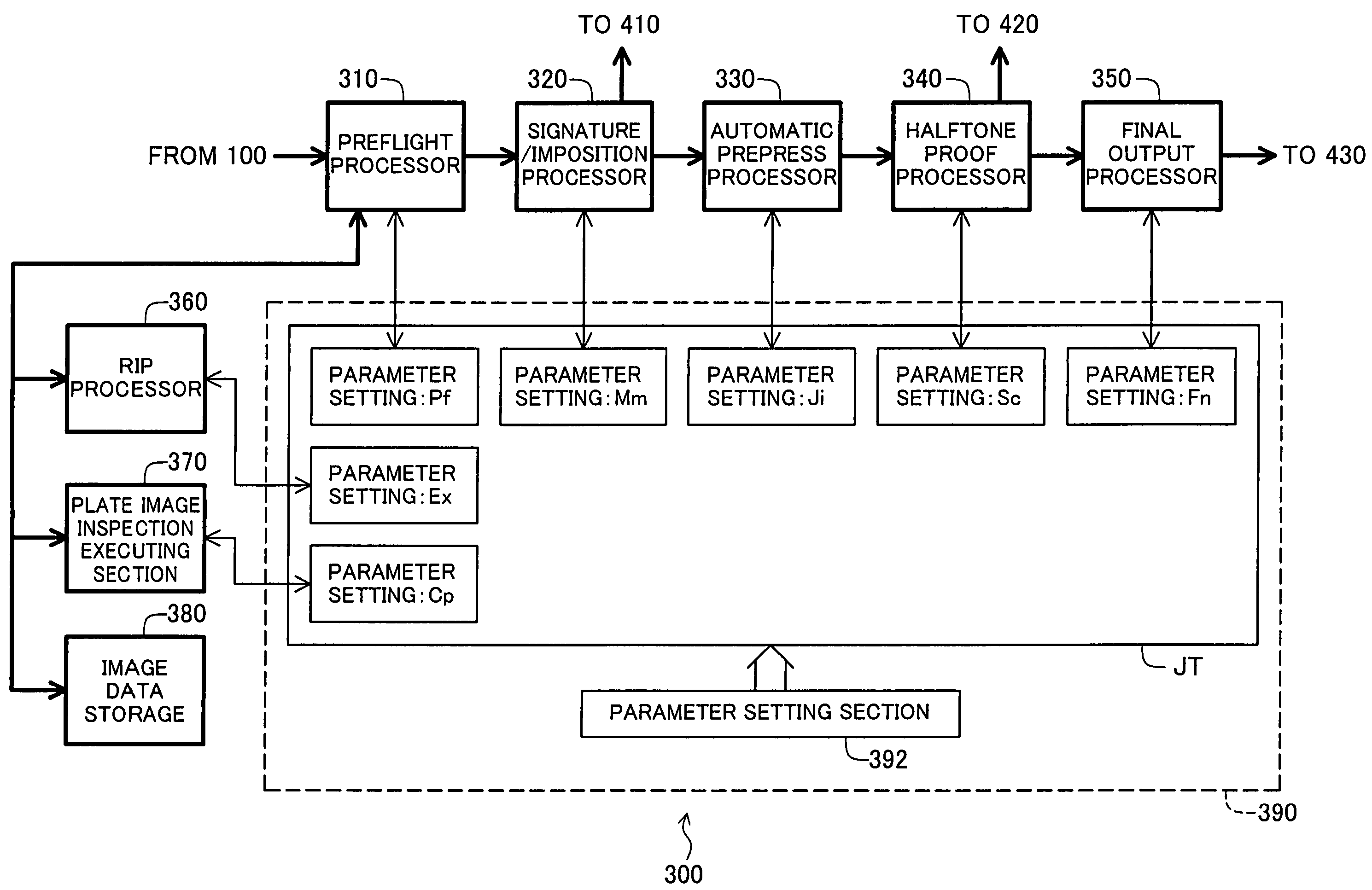
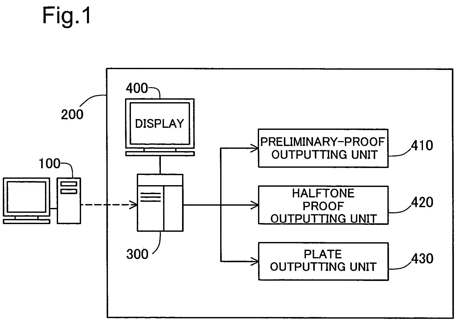
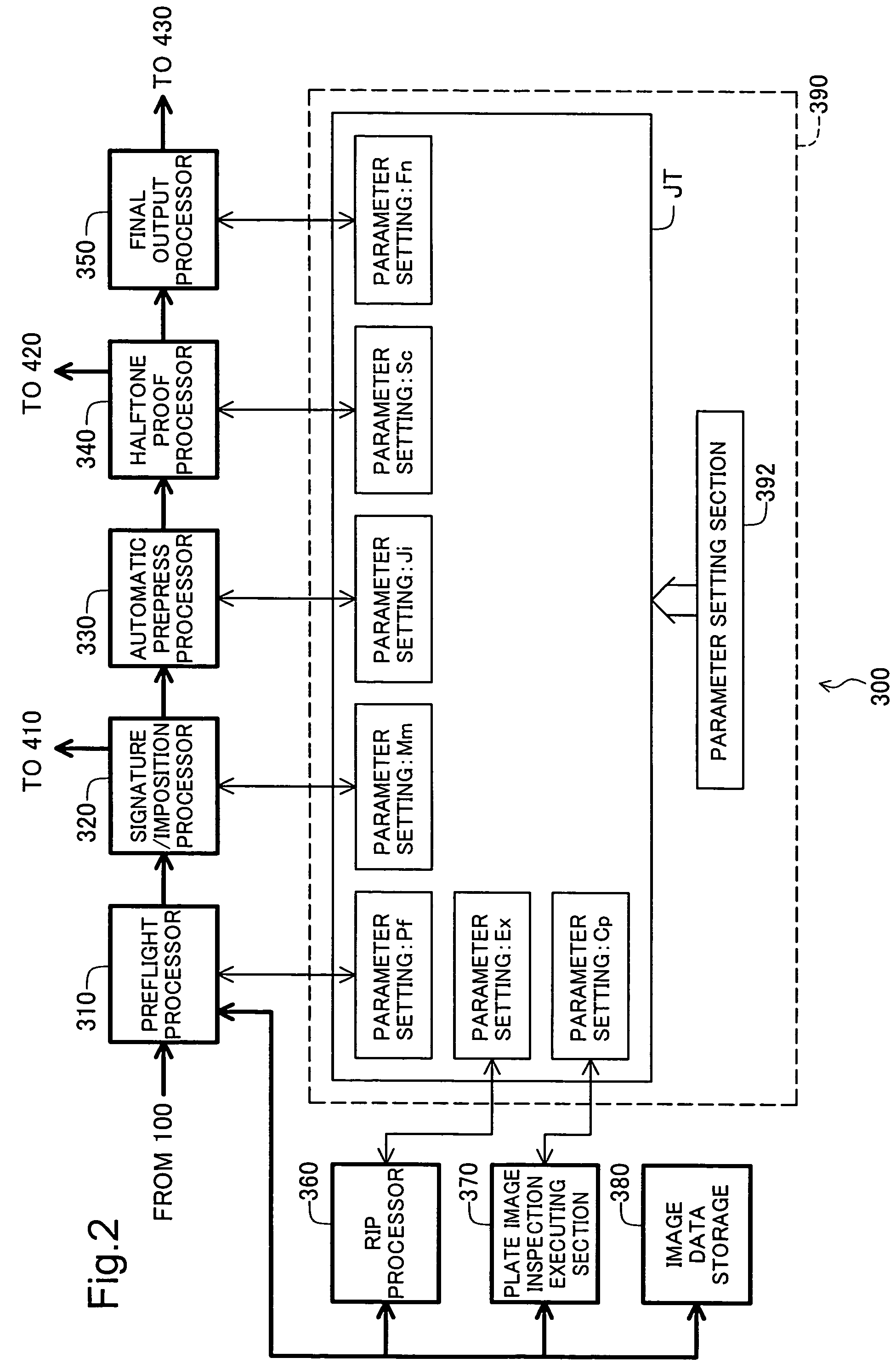
[0054]FIG. 4 illustrates plate image inspection using raster image data (corresponds to “plate image inspection 1” in FIG. 3). Plate image inspection in this embodiment is executed in order to inspect for differences between proofed print image data (second print image data) created by design device 100 (FIG. 1) and print image data prior to proofing (first print image data). Proofed print image data is created by design device 100 in the event that correction of the original has become necessary as a result of the aforementioned flow pattern proofing or inspection.
[0055]When print image data prior to proofing (first print image data) PDa is received by workflow control system 300 (FIG. 1, FIG. 2), its content is analyzed by preflight processor 310 to verify whether the prepress process can be executed without major problems. Print image data PDa is developed by raster image processor 360 to display resolution for the purpose of display of a...
embodiment 2
B3. Embodiment 2 of Plate Image Inspection
[0067]FIG. 7 illustrates a second embodiment of plate image inspection. The difference from the embodiment 1 is that the user can set the reference image position in a print area for development of print image data to display resolution by raster image processor 360a. That is, instead of a predetermined reference position, raster image processor 360a uses a desired reference position POS set by the user, to execute development of print image data PDb. Plate image inspection processor 370 executes a plate image inspection process using first raster image data IMDa stored in image data storage 380, and second raster image data IMDb that has been developed according to the selected reference position POS, and displays the results of the plate image inspection process on display device 400.
[0068]FIGS. 8(a) through 8(c) illustrate the effect of reference position on the pixel value difference. Image PD1 and image PD2 shown in FIG. 8(a) are both r...
embodiment 3
B4. Embodiment 3 of Plate Image Inspection
[0074]FIG. 10 is an illustration of plate image inspection results screen shown on display device 400 in this embodiment. The difference from the results shown in FIGS. 9(a) and 9(b) is that the print area in which print image data is displayed is divided into a plurality of areas, with reference position independently settable in each of this plurality of areas. The plate image inspection process image IMG shown on the screen in FIG. 10 is divided into a plurality of areas DR (in this example, 5×5 for a total of 25 areas), with the selected area shown highlighted. Each area is composed of a given number of display pixels. Using position adjusting section BM, the user moves the reference position of a selected area, whereupon the distance that the reference position was moved in the selected area is indicated by movement distance display section IM.
[0075]In each area in plate image inspection process image IMG there is displayed a plate imag...
PUM
 Abstract
Description
Claims
Application Information