
Method of using a cutting edge cart

a cutting edge and cart technology, applied in the field of bladed devices, can solve the problems of cutting edge wear with use, permanent wear/damage to the permanent structure of the mold board, particularly earth and/or snow moving equipment, etc., to achieve the effect of reducing the number of parts, easy manufacturing and convenient storag

Inactive Publication Date: 2007-06-05
BLADE ELEVATOR
View PDF5 Cites 1 Cited by
  • Summary
  • Abstract
  • Description
  • Claims
  • Application Information

AI Technical Summary

Benefits of technology

"The present invention provides an apparatus for selectively positioning a cutting edge relative to the mold board of bladed equipment for attachment or removal. The apparatus includes a cart with a frame and transport members that allow the cutting edge to be raised and lowered to a desired vertical position. The apparatus is easy to use, with a single operator able to handle the replacement cutting edge. The apparatus is also designed to be easily manufactured and stored when not in use. The technical effects of the invention include improved efficiency and ease of use for replacing cutting edges on bladed equipment."

Problems solved by technology

Though made from durable steel, these cutting edges wear with usage.
Upon reaching a predetermined amount of wear, these cutting edges must be replaced to prevent the bottom edge of the mold board from contacting the ground during use, thus causing permanent wear / damage to the permanent structure of the mold board.
Earth and / or snow moving equipment, and particularly earth and / or snow moving equipment utilized to grade / plow roads (i.e. a “road grader” or “patrol”) are especially susceptible to heavy wear of their cutting edges, as they are often used to move highly abrasive materials such as gravel and asphalt.
As a result, operations that utilize this type of equipment, such as road construction firms and governmental entities that are responsible for maintaining existing roads, spend a considerable amount of time replacing these cutting edges.
The replacement of blade edges is generally time consuming and represents down time for the equipment.
Even though these cutting edges may be separated into several sections, they may still be up to about 12 feet long and, as a metal plate, be quite heavy and awkward to handle.

Method used


Image

  • Method of using a cutting edge cart
  • Method of using a cutting edge cart
  • Method of using a cutting edge cart

Examples


Embodiment Construction

[0040]In the following description, the cutting edge handling cart is set forth primarily in the context of replacing cutting edges bolted to the forward edge of a mold board on a road grader vehicle. However, the present invention is also applicable for replacing the cutting edges on a mold board of a snow plow-type device or any other bladed machinery.

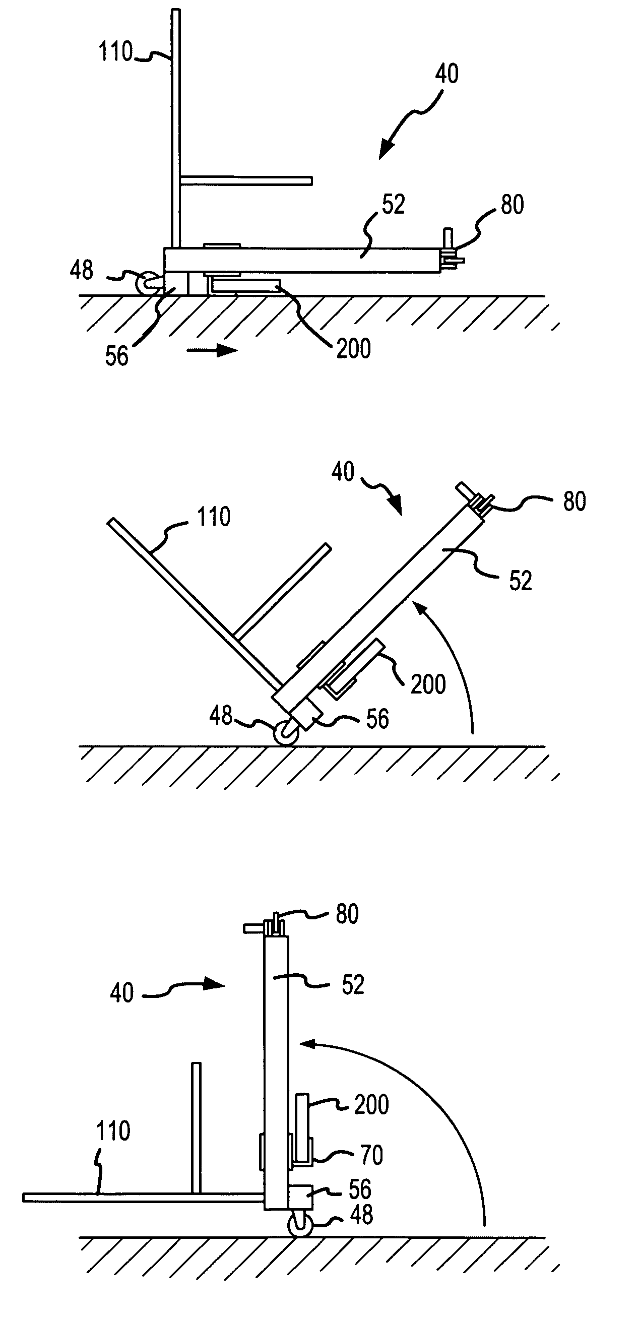
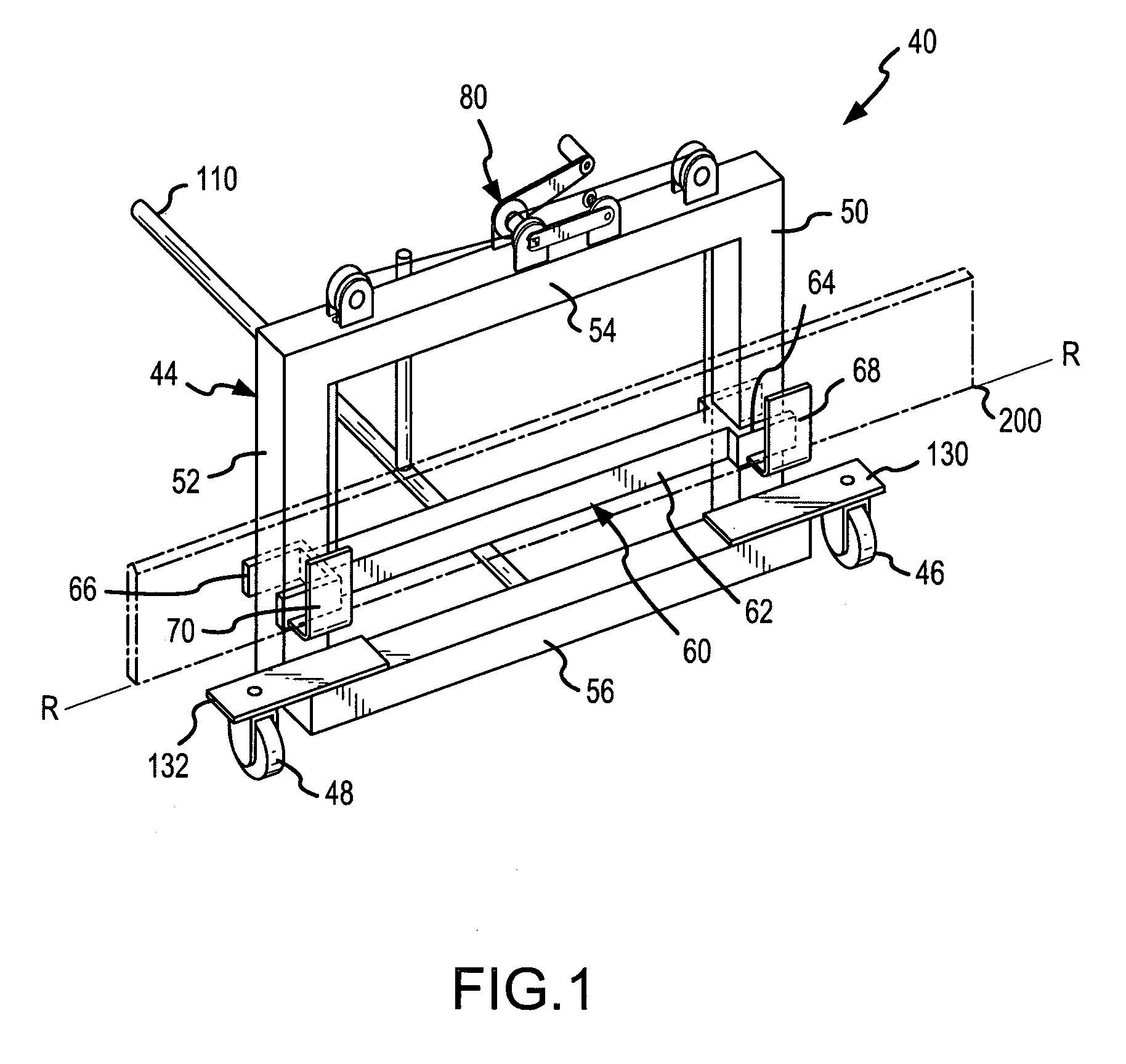
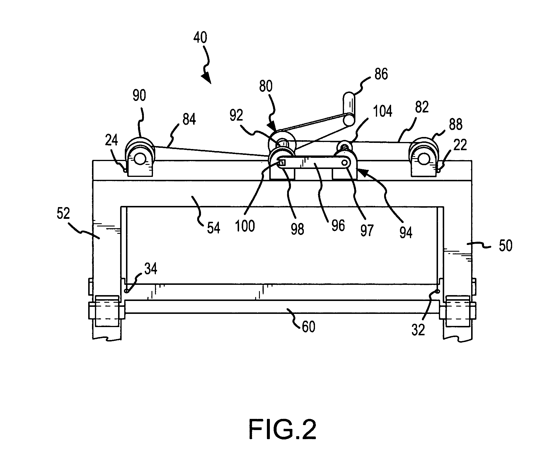
[0041]FIG. 1 is a perspective view of one embodiment of a cutting edge handling cart 40 (hereinafter “cart”). The cart 40 may be utilized to retrieve and transport a cutting edge 200 (shown in phantom in FIG. 1) and position that cutting edge 200 relative to a mold board 210 on a road grader vehicle for attachment thereto (see FIG. 4), as well as to facilitate the removal of such a cutting edge 200 from a mold board 210. The cart 40 generally includes a frame 44, a carrier assembly 60 slidably mounted to the frame 44 so as to move at least generally within a reference plane, cutting edge supports 68, 70, wheels 46, 48, an adjuster 80...


PUM

PropertyMeasurementUnit
lengthaaaaaaaaaa
lengthaaaaaaaaaa
lengthaaaaaaaaaa

Abstract

A cutting edge cart is disclosed that provides an improved means for replacing the replaceable cutting edges on bladed equipment such as road graders and snow plow. The cart allows a single user to retrieve, transport, and position a replacement cutting edge relative to a mold board of the bladed equipment. Generally, the cart contains a frame, two or more transport assemblies attached to the frame, such as wheels, a movable carrier assembly that contains a cutting edge support assembly, and an adjuster. The adjuster is operable to move the carrier assembly between first and second positions relative to the frame allowing the vertical position of a supported cutting edge to be adjusted. The frame and transport assemblies are disposed such that the cart may be rotated or pivoted from a first generally vertical position to a second generally horizontal position. In this horizontal position, a cutting edge may be received within the cutting edge support and the cart rotated back to the generally vertical position.

Description

CROSS REFERENCE TO RELATED APPLICATIONS[0001]This patent application is a divisional of and claims priority under 35 U.S.C. § 120 to U.S. patent application Ser. No. 10 / 304,530, that was filed on Nov. 26, 2002 now U.S. Pat. No. 6,964,092, and that is entitled “CUTTING EDGE CART,” the entire disclosure of which is incorporated by reference herein.FIELD OF THE INVENTION[0002]The present invention relates generally to bladed devices such as snow plows and earth working machinery. More particularly, the present invention relates to a blade or cutting edge handling cart for replacing blades / cutting edges that are typically releasably affixed to bladed devices.BACKGROUND[0003]Earth working and snow removal equipment generally utilize a blade that is contacted with the ground to scrape away or “grade” a desired surface. Generally, the blade can be defined as having two main parts; a long support member, also referred to as a mold board, and a replaceable cutting edge interconnected to and ...

Claims


Application Information

Patent Timeline
Patent Type & Authority Patents(United States)
IPC IPC(8): B23Q3/00B23Q7/00B23Q15/00B62B1/26B62B5/06
CPCB62B1/262B62B1/268B62B5/06B62B2203/10Y10T29/49895Y10T29/53091Y10T29/49998Y10T29/53896Y10T29/53961Y10T29/53909Y10T29/49901
Inventor LORENZ, DONALD E.QUAM, DONALD W.
Owner BLADE ELEVATOR
Learn More