Nano-electrode-array for integrated circuit interconnects

Active Publication Date: 2007-06-05
KLA TENCOR CORP
View PDF12 Cites 24 Cited by
  • Summary
  • Abstract
  • Description
  • Claims
  • Application Information

AI Technical Summary

Problems solved by technology

This diffusion can result in a conductive buildup and cause short circuits in the integrated circuits.
A problem exists in forming very thin layers of a uniform thickness for integrated circuits.
A problem occurs with high resistance in the interconnects with decreasing size which reduce the advantage of using high conductivity materials, such as copper, which are

Method used


Image

  • Nano-electrode-array for integrated circuit interconnects
  • Nano-electrode-array for integrated circuit interconnects
  • Nano-electrode-array for integrated circuit interconnects

Examples


Embodiment Construction

[0036]In the following description, numerous specific details are given to provide a thorough understanding of the invention. However, it will be apparent that the invention may be practiced without these specific details. In order to avoid obscuring the present invention, some well-known circuitry and process steps are not disclosed in detail.

[0037]Likewise, the drawings showing embodiments of the transistor are semi-diagrammatic and not to scale and, particularly, some of the dimensions are for the clarity of presentation and are shown greatly exaggerated in the FIGs.

[0038]In addition, where multiple embodiments are disclosed and described having some features in common, for clarity and ease of illustration, description, and comprehension thereof, similar and like features one to another will ordinarily be described with like reference numerals.

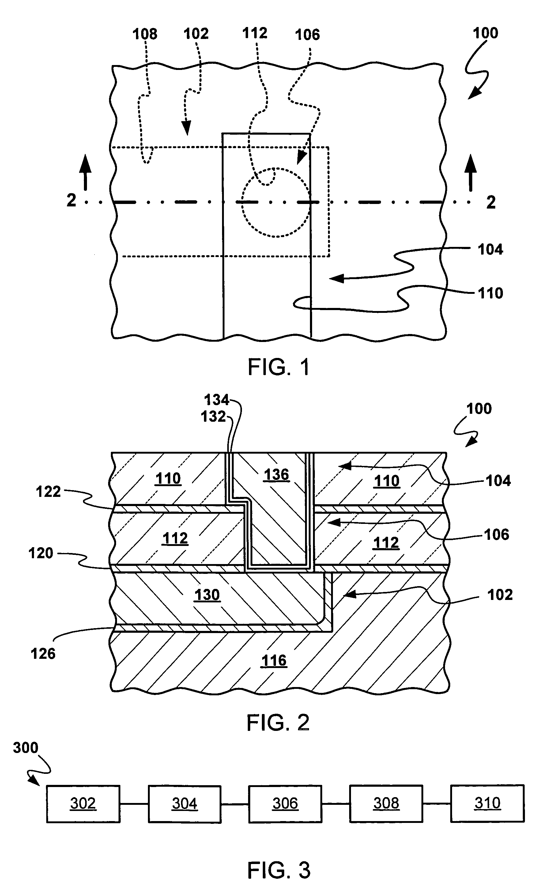
[0039]Referring now to FIG. 1, therein is shown a plan view of an integrated circuit 100 in accordance with an embodiment of the present i...


PUM


Abstract

An integrated circuit and a method of manufacturing an integrated circuit is provided including providing an integrated circuit having a trench and via provided in a dielectric layer. A nano-electrode-array is formed over the dielectric layer in the trench and via, and a conductor is deposited over the nano-electrode-array. The conductor and the nano-electrode-array are coplanar with a surface of the dielectric layer.

Description

TECHNICAL FIELD[0001]The present invention relates generally to semiconductor technology and more specifically to integrated circuit interconnects.BACKGROUND ART[0002]In integrated circuits, transistors are made on a semiconductor substrate and connected together using integrated circuit interconnects. This process is performed using a number of different photolithographic, deposition, and removal processes to create contacts to the transistors, trenches to the contacts, and vias interconnecting the trenches where there are more than one level of channels.[0003]Generally, a device dielectric layer is deposited over the transistors, openings are formed through the device dielectric layer down to transistor junctions and gates, and the openings are filled with a conductive metal to form contacts.[0004]In one technique called the “single damascene” process, the formation of the first trenches starts with the deposition of a thin first trench stop layer over the device dielectric layer....

Claims


Application Information

Patent Timeline
IPC IPC(8): H01L21/4763
CPCH01L21/76843H01L21/76844H01L21/76846H01L21/76868H01L21/76874Y10S977/723
Inventor LOPATIN, SERGEY D.FIORDALICE, ROBERTPINTCHOVSKI, FAIVELIVANOV, IGORKONG, WEN Z.KOLICS, ARTUR
Owner KLA TENCOR CORP
Why Eureka
Try Eureka