Radar fill-level sensing device

a sensing device and radar technology, applied in the direction of engine lubrication, liquid/fluent solid measurement, reradiation, etc., can solve the problems of reducing the reproducibility of the process, affecting the effect of the process, and unable to render the ignition of an explodible gas mixtur

Active Publication Date: 2007-06-05
KROHNE SA
View PDF10 Cites 9 Cited by
  • Summary
  • Abstract
  • Description
  • Claims
  • Application Information

AI Technical Summary

Benefits of technology

[0015]It is, therefore, the objective of this invention to introduce a radar fill-level sensing device of the type described that can easily and reproducibly be designed along the “intrinsically safe” ignition-protection classification.
[0019]While the length of the first segment of the ground conductor should essentially correspond to one quarter of the predefined wavelength of the radar signals, the length of the second segment of the ground conductor is less critical. However, in a preferred embodiment of the invention, the length of the second segment is less than half the predefined wavelength. Preferably, the length of the second segment is essentially selected between one eighth and three eighths of the predefined wavelength. But here as well, the length of the second segment most preferably corresponds to one quarter of the predefined wavelength.

Problems solved by technology

What this means is that in the intrinsically safe power supply the voltage and current will always be so small that in the event of a is short circuit, a power interruption or a ground fault, the ignition energy will always remain below the minimum ignition energy, rendering the ignition of an explosible gas mixture impossible.
However, the drawback of the design described in U.S. 2004 / 0066588 A1 is its poor reproducibility.
Moreover, grounding provisions of the type described are difficult to simulate since drilling through the board and, respectively, providing the other side with the grounding layer must take into account the numerical simulation methods employed, which significantly adds to the complexity of the process.

Method used


Image

  • Radar fill-level sensing device
  • Radar fill-level sensing device
  • Radar fill-level sensing device

Examples


Embodiment Construction

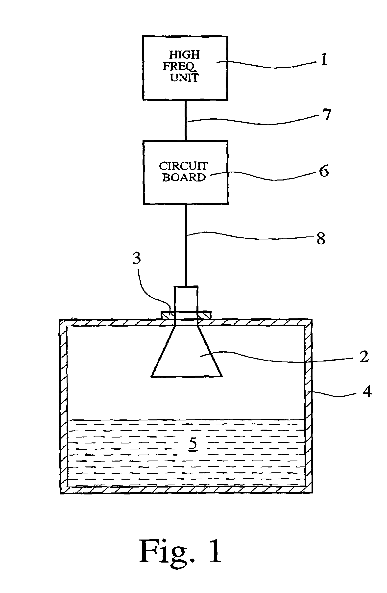
[0026]The radar fill-level sensing device according to a preferred embodiment, shown in FIG. 1, encompasses a high-frequency unit 1 serving to generate and process radar signals of a predefined frequency, typically on the order of several GHz which corresponds to wavelengths of several centimeters. The antenna 2 serving to transmit and receive radar signals is a horn antenna, although a rod antenna would be equally suitable.

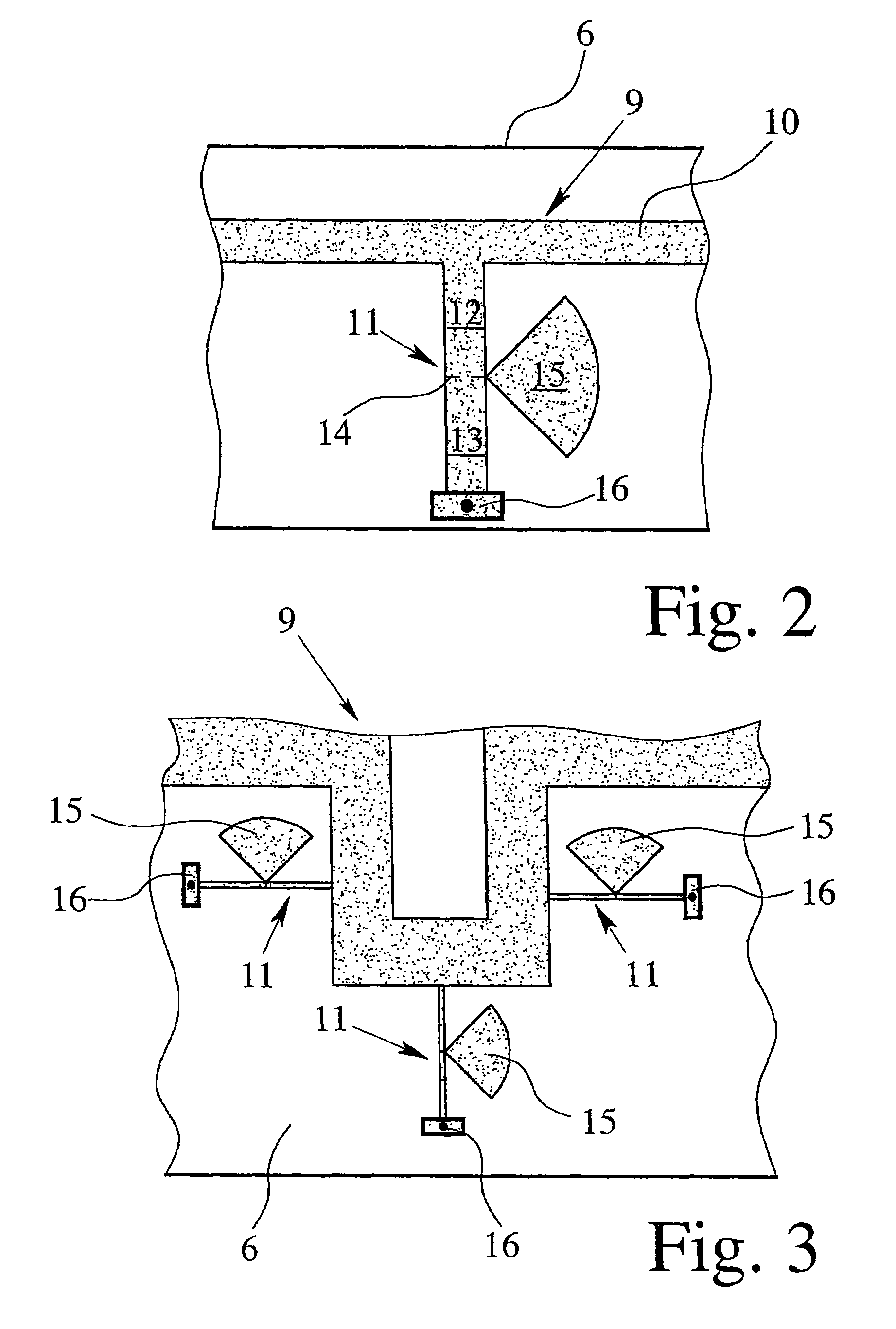
[0027]By way of a flange mount or screw connection 3, the antenna 2 is positioned in a container 4 that holds a substance 5 whose fill level is to be determined. Interpositioned between the high-frequency unit 1 and the antenna 2 is a circuit board 6 that connects to the high-frequency unit 1 via a lead 7 and to the antenna 2 via a lead 8. FIGS. 2 and 3 show details of a possible configuration of the circuit board 6.

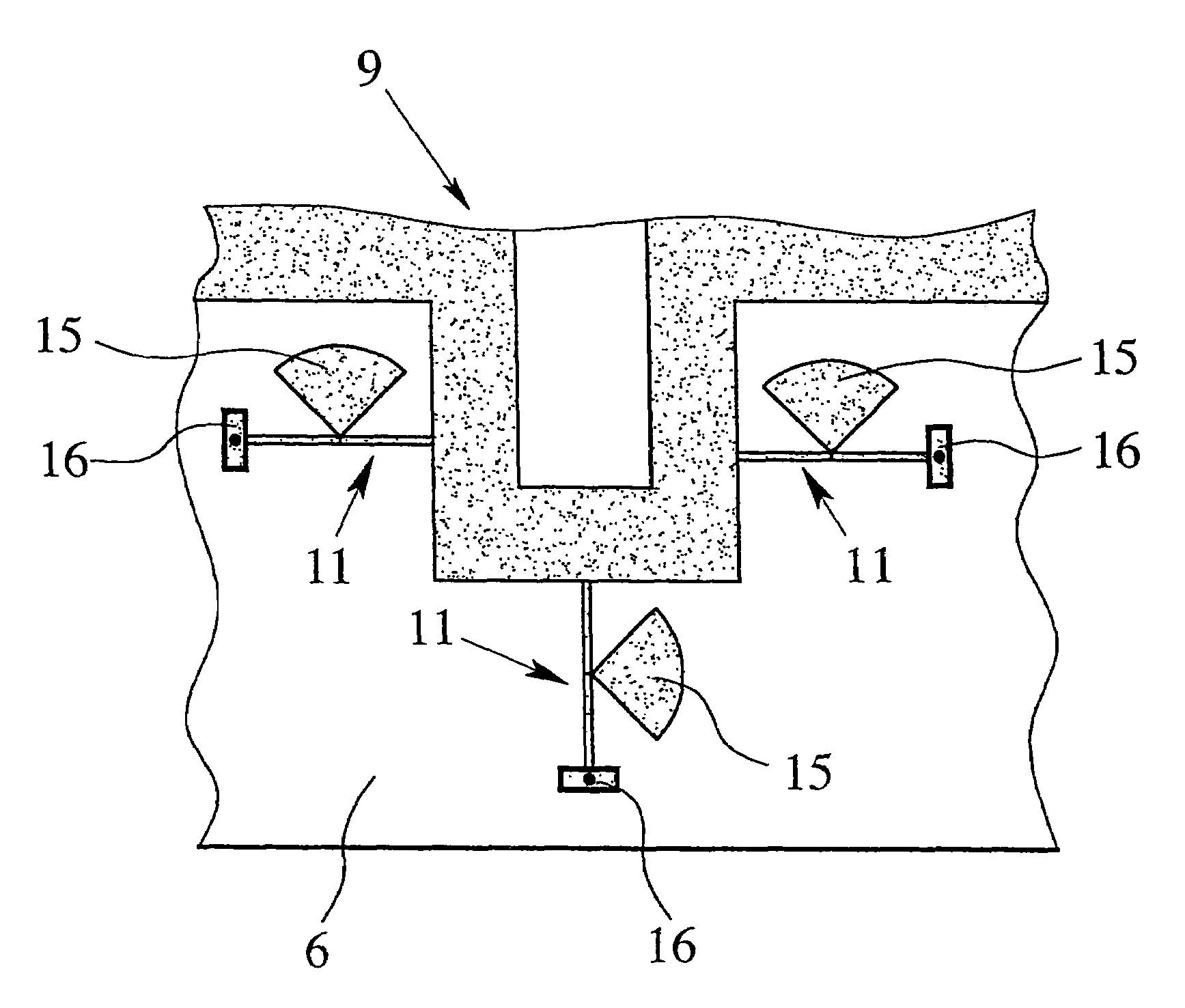
[0028]FIG. 2 shows part of the configuration of the board 6 according to a first preferred embodiment of the invention. As can be seen in FIG. 2, one...


PUM


Abstract

A radar fill-level sensing device has a high-frequency unit that serves to generate and process radar signals of a predefined frequency and wavelength, an antenna for transmitting and / or receiving the radar signals, as well as circuitry, provided on a circuit board. That circuitry includes a microstrip circuit for connecting the high-frequency unit to the antenna, that microstrip circuit featuring a ground conductor. The ground conductor encompasses a first segment, a radial stub and a second segment, the length of the first segment corresponding essentially to one quarter of the predefined wavelength. The radial stub is positioned at the end of the first segment, the second segment connects to the end of the first segment and to the radial stub, and the second segment is grounded. Based on this design, a radar fill-level sensing device is obtained that can easily and reproducibly be implemented within the requirements of “intrinsically safe” ignition protection.

Description

BACKGROUND OF THE INVENTION[0001]1. Field of the Invention[0002]This invention relates to a radar fill-level sensing device encompassing a high-frequency unit that serves to generate and process radar signals at a predefined frequency and wavelength, an antenna for sending and / or receiving radar signals, as well as board-mounted microstrip circuitry for connecting the high-frequency device to the antenna, said microstrip circuitry including a ground conductor. A radar fill-level sensing device of this type has been described earlier, for instance in U.S. 2004 / 0066588 A1.[0003]2. The Prior Art[0004]Industrial applications often involve the need to measure the fill level of a substance, for instance a liquid or a bulk material, in a container such as a tank. This has been accomplished by a variety of techniques, differentiated between contact and non-contact level sensing methods. Contact level sensing methods whereby a component of the sensing device makes contact with the substance ...

Claims


Application Information

Patent Timeline
Patent Type & Authority Patents(United States)
IPC IPC(8): G01S13/08G01F23/284H01P1/203
CPCG01F23/284
Inventor BLETZ, ACHIMMUSCH, THOMAS
Owner KROHNE SA
Why Eureka
Try Eureka