Wide-range, wide-angle compound zoom with simplified zooming structure

a compound zoom and wide-angle technology, applied in the field of zoom lenses, can solve the problems of general limitations in design, and achieve the effect of simple structur

Active Publication Date: 2007-06-05
PANAVISION INT LP +1
View PDF24 Cites 44 Cited by
  • Summary
  • Abstract
  • Description
  • Claims
  • Application Information

AI Technical Summary

Benefits of technology

[0011]Embodiments of the present invention represent an improvement to the compound zoom design described in related U.S. patent application Ser. No. 11 / 071,125 that reduces the number of independently moving lens groups to just two or three while retaining a large zoom ratio and maintaining or enlarging the field of view at the shortest focal length. The compound zoom system according to embodiments of the present invention can also utilize the zooming groups as focusing groups and for athermalization, thus maintaining a relatively simple mechanical structure. It is to be understood that temperature changes may cause the lens to go out of focus, so additional movement of the zooming groups (similar to moving the zooming groups for focusing) compensates for these temperature changes. This temperature compensation is referred to as athermalization.
[0015]The optical design consists of a zooming kernel followed by a zooming relay, with a stationary P lens group in between. The zooming kernel has either an NP or NPP structure, and the zooming relay has either a P or PP structure. The kernel, as defined herein, includes all lens groups on the object space side of the stationary P lens group, while the zooming relay includes all zoom groups on the image space side of the stationary P lens group. There are just two or three independently moving groups altogether, one or two on each side of the intermediate image. The front group is stationary with respect to the image plane, as are the fold prisms. The zooming relay, comprising just one or two independently moving positive groups, has a notably simple structure that contributes significantly to the simplicity of the system as a whole.

Problems solved by technology

Although it is possible to design wide-range zooms with conventional non-compound technology, such designs are generally limited at the wide end to a 35 mm format equivalent focal length of about 24 to 28 mm.

Method used


Image

  • Wide-range, wide-angle compound zoom with simplified zooming structure
  • Wide-range, wide-angle compound zoom with simplified zooming structure
  • Wide-range, wide-angle compound zoom with simplified zooming structure

Examples


Embodiment Construction

[0062]In the following description of preferred embodiments, reference is made to the accompanying drawings that form a part hereof, and in which is shown by way of illustration specific embodiments in which the invention may be practiced. It is to be understood that other embodiments may be utilized and structural changes may be made without departing from the scope of the preferred embodiments of the present invention.

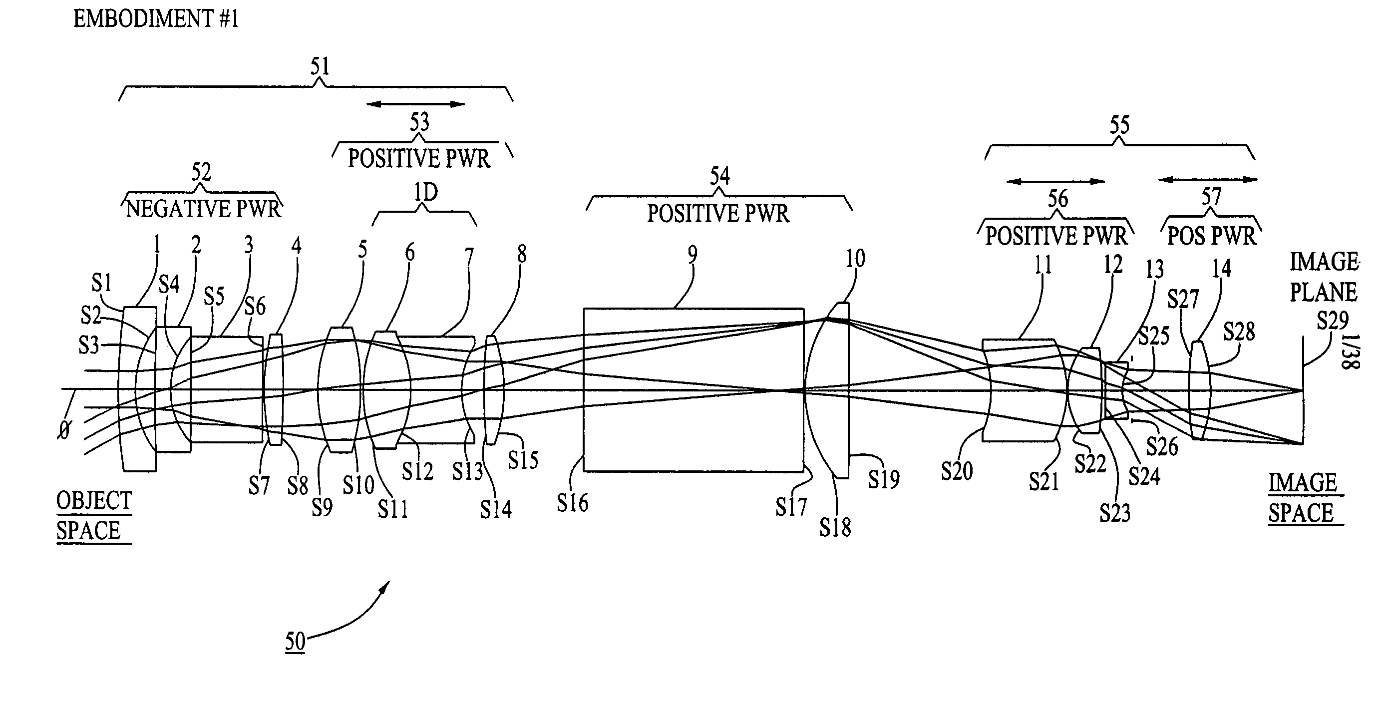
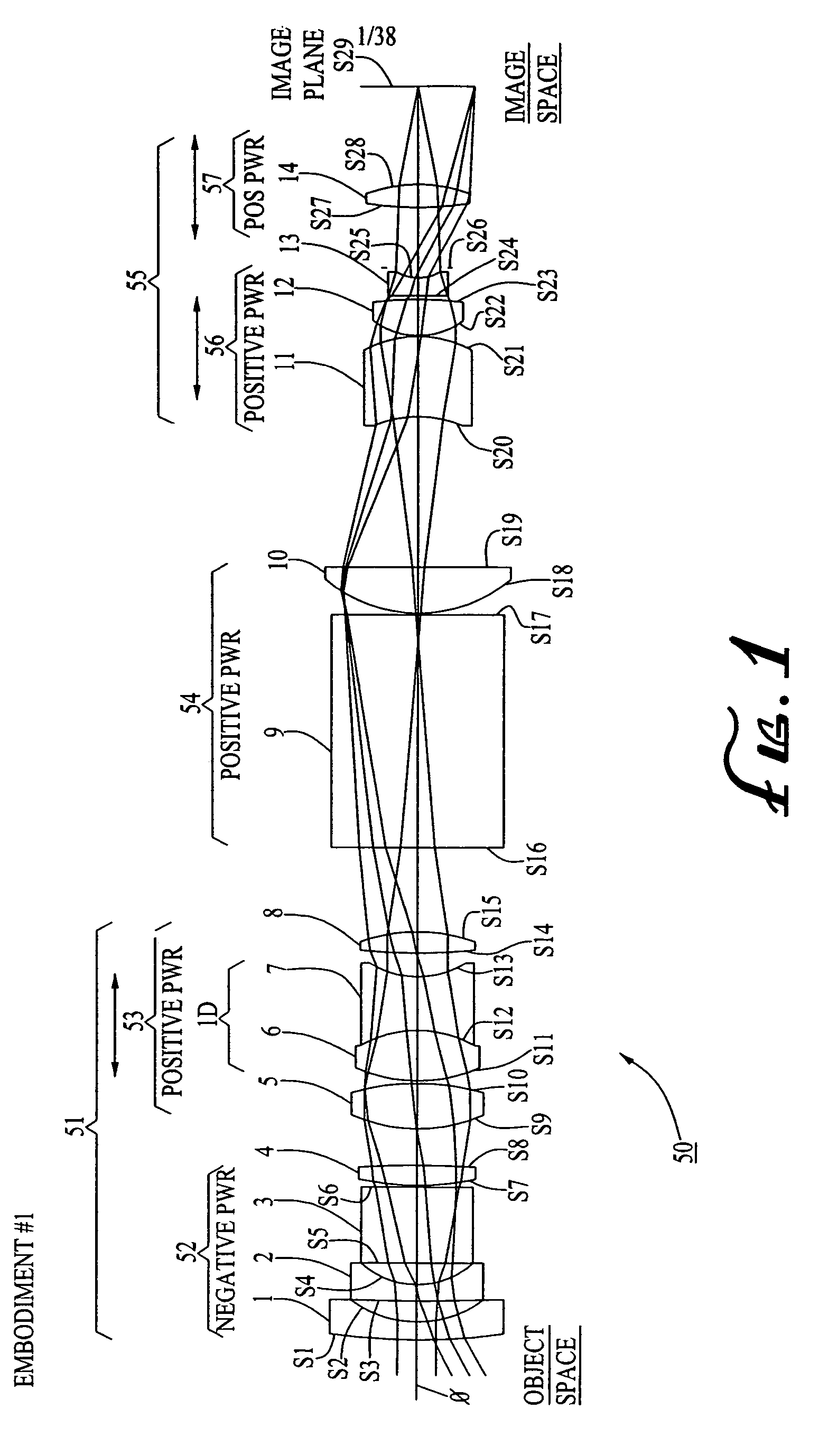
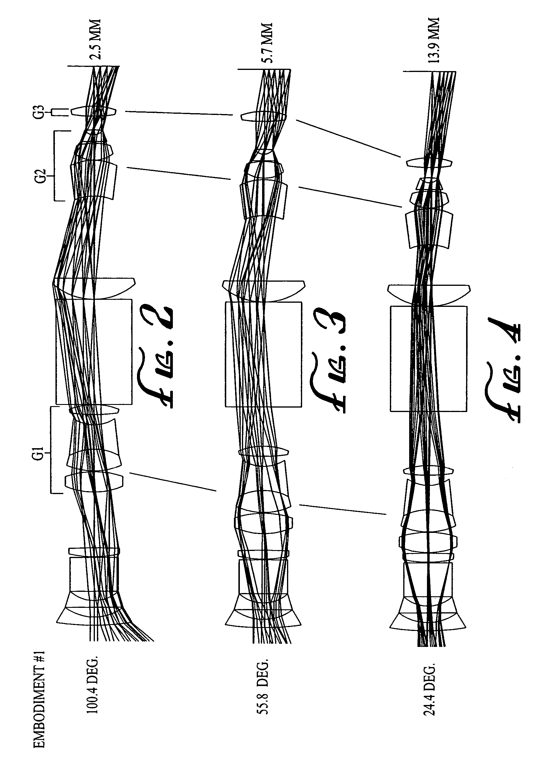
[0063]Embodiments of the present invention are directed to an optionally rotatable compound zoom design having only two or three independently moving lens groups, a large zoom ratio and a wide field of view at the shortest focal length, and having sufficient performance to be used with a 3 megapixel class sensor with a pixel size of 2.4 μm. The compound zoom system according to embodiments of the present invention can also utilize the zooming groups as focusing groups and for athermalization, thus maintaining a relatively simple mechanical structure.

[0064]First exemp...


PUM


Abstract

A zoom lens is disclosed having a zoom ratio larger than four with a field of view at the short focal length position larger than 85 degrees and with a minimal number of moving groups. The zoom lens utilizes a compound zoom structure comprising an NP or NPP zoom kernel followed by a P or PP zoom relay, with only two or three moving groups that can be used for both zooming, focusing and athermalization. An overall compact package size is achieved by the use of prisms to fold the optical path in strategic locations. An optional variable power liquid cell can provide close focusing with little or no focus breathing.

Description

CROSS-REFERENCE TO RELATED APPLICATIONS[0001]This application is related to U.S. Patent Application Publication No. 20040021953, filed on Jul. 18, 2003, and U.S. patent application Ser. No. 11 / 071,125, filed on Mar. 2, 2005, the contents of which are incorporated by reference herein.BACKGROUND OF THE INVENTION[0002]1. Field of the Invention[0003]The present invention relates, generally, to zoom lenses, and in particular embodiments, to an optionally rotatable compound zoom lens with a minimal number of moving lens groups that provides a wide focal length range and a wide field of view and is small in size to fit in consumer products such as cellular telephones and other products with compact lenses.[0004]2. Description of Related Art[0005]Notably lacking in the prior art are zoom lenses having a zoom ratio greater than about four combined with a maximum field of view at the short focal length position of 85 degrees or more. Although such zoom lenses are known in the field of broadca...

Claims


Application Information

Patent Timeline
Patent Type & Authority Patents(United States)
IPC IPC(8): G02B23/00G02B15/14
CPCG02B15/177G02B7/008G02B5/04G02B15/143G02B3/12G02B7/00G02B13/18
Inventor CALDWELL, JAMES BRIANNEIL, IAIN A.
Owner PANAVISION INT LP
Why Eureka
Try Eureka