Thin film interleaver

a technology of interleaver and thin film, applied in the field of systems and methods for interleaving optical signals, can solve the problems of significant signal loss, high signal loss, and temperature sensitivities of the fused fiber interleaver device itself, and achieve the effect of reducing cross talk and reducing insertion loss

Active Publication Date: 2007-06-05
II VI DELAWARE INC
View PDF45 Cites 3 Cited by
  • Summary
  • Abstract
  • Description
  • Claims
  • Application Information

AI Technical Summary

Benefits of technology

[0016]The thin film interleaver includes, in one embodiment, a dual fiber collimator that has an input fiber and a reflection fiber. A thin film is attached on the dual fiber collimator. The thin film is designed such that it exhibits a flat top frequency response and such that it reflects a first set of wavelengths while allowing a second set of wavelengths to pass through the thin film. Each of the wavelengths in the first set is adjacent to one of the wavelengths in the second set of wavelengths in one embodiment. The thin film interleaver exhibits lower insertion loss across the bandwidth of channels and exhibits lower cross talk between adjacent channels.
[0017]Additional features and advantages of the invention will be set forth in the description that follows, and in part will be obvious from the description, or may be learned by the practice of the invention. The features and advantages of the invention may be realized and obtained by means of the instruments and combinations particularly pointed out in the appended claims.

Problems solved by technology

One of the challenges in modern optical multiplexing systems is addressing the temperature sensitivities of the optical equipment.
Further, the fused fiber interleaver device itself has some temperature sensitivities.
As the channel wavelength drifts away from the carrier wavelength, the response quickly drops off, resulting in higher signal loss.
In other words, wavelength drift can result is significant signal loss.
Heavy losses of signal power are less tolerable, as they can reduce the distances over which the optical network can be deployed and can increase error rates.
A drawback from having a wider frequency response is that adjacent channels become less isolated as the actual frequency varies from the defined channel frequency.
Cross-talk results in data from one channel being mixed into adjacent channels thus making the data on the adjacent channel more difficult or impossible to extract.
Adjusting either the frequency dependent loss or cross talk performance characteristics has an adverse affect on the other.

Method used


Image

  • Thin film interleaver
  • Thin film interleaver
  • Thin film interleaver

Examples


Embodiment Construction

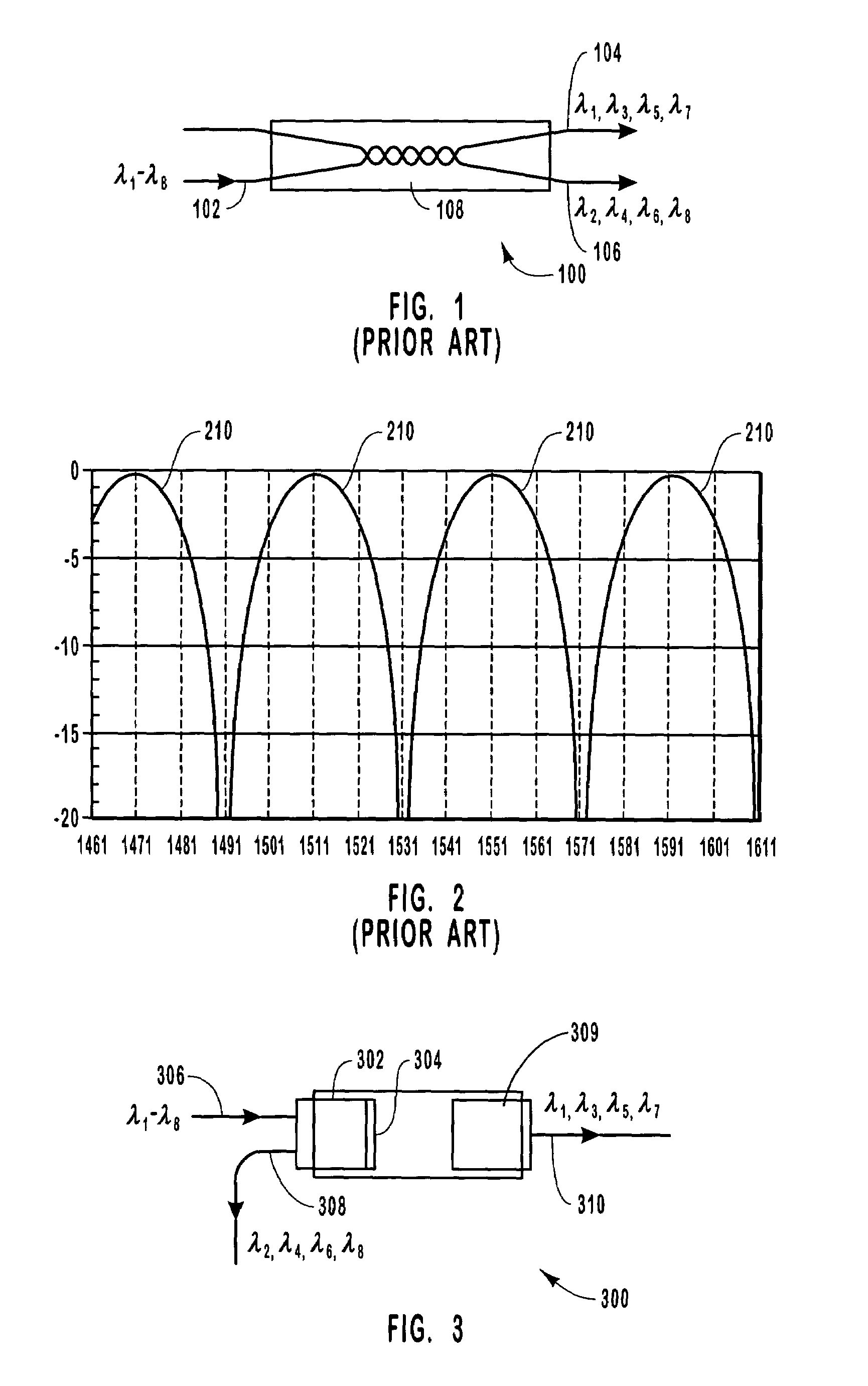
[0025]Interleavers are optical elements or components that can be used for a variety of different purposes. Often, interleavers are used in multiplexing or demultiplexing optical elements as well as in add / drop multiplexers to separate or combine two sets of optical signals. Fused fiber interleavers have a Gaussian response. Thus, the signal loss of a fused fiber interleaver can increase when the interleaver or optical signals are subject, for example, to wavelength drift, temperature variations, and the like.

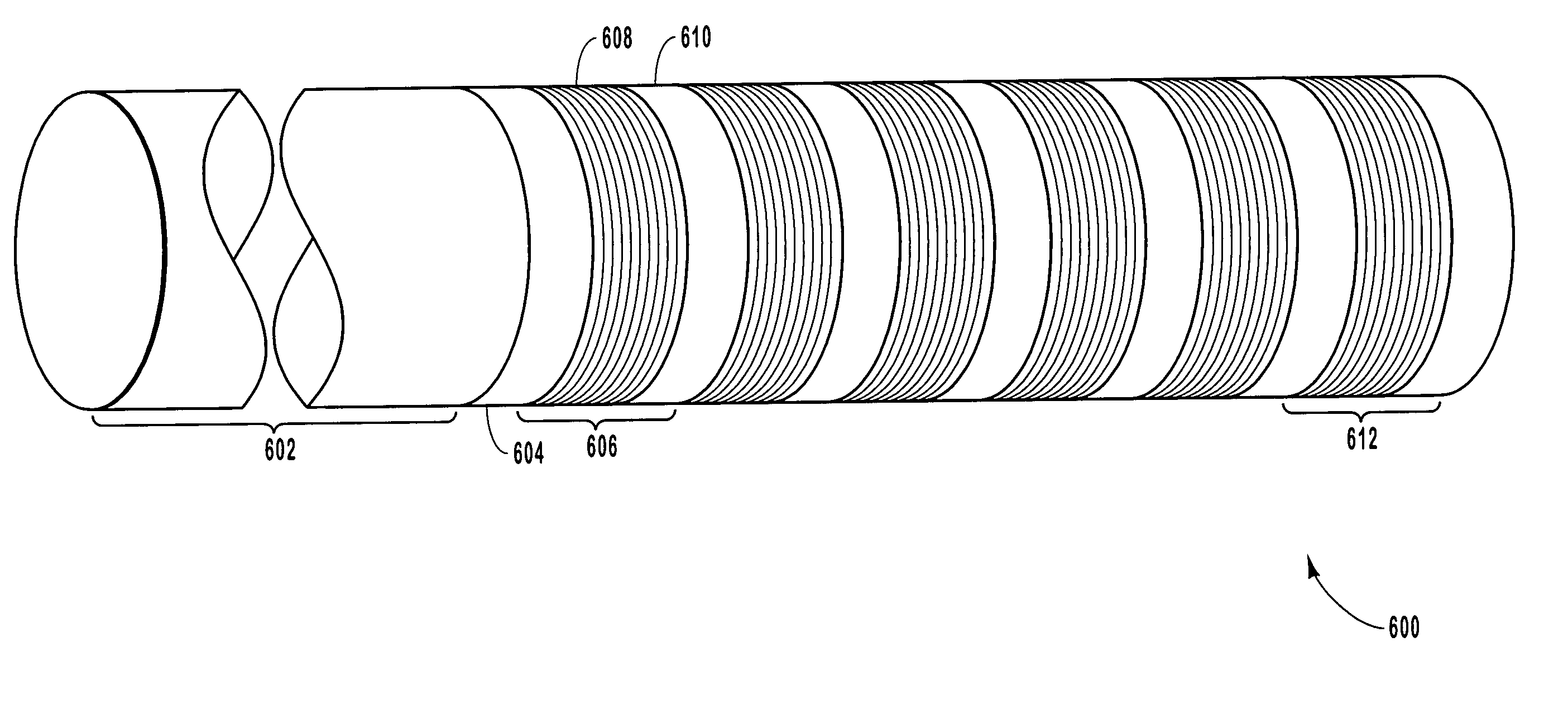
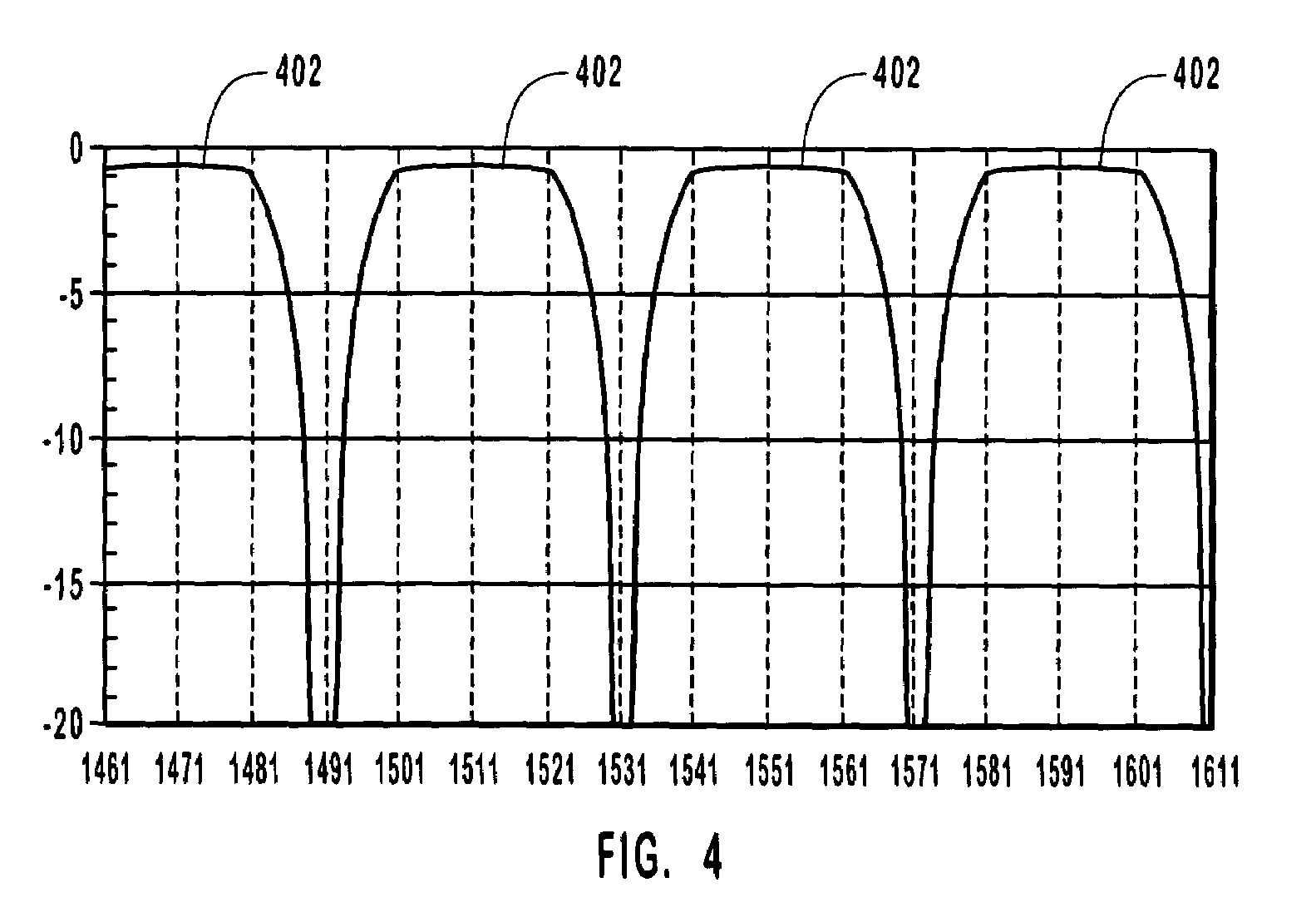
[0026]The present invention relates to interleavers and more particularly to a thin film interleaver. A thin film interleaver has the advantage of providing an improved frequency response that is not as susceptible to wavelength drift and temperature variations. The present invention also relates to optical elements such as multiplexers and demultiplexers that incorporate both fused fiber interleavers and thin film interleavers.

[0027]In one embodiment of a thin film interleaver...


PUM


Abstract

A thin film interleaver device is disclosed. The thin film interleaver includes thin film optics. The thin film(s) are formed such that they reflect one group of wavelengths while allowing a second group of wavelengths to pass through the thin film(s). The thin film(s) exhibit a flat top frequency response across the channel bandwidths of the multiplexed signal for which the thin film filter is designed such that the thin film interleaver is less sensitive to wavelength drift and temperature variations.

Description

CROSS-REFERENCE TO RELATED APPLICATIONS[0001]This application claims the benefit of U.S. Provisional Application No. 60 / 422,742, titled THIN FILM INTERLEAVER filed Oct. 31, 2002, which is incorporated herein by reference.BACKGROUND OF THE INVENTION[0002]1. The Field of the Invention[0003]The present invention relates to systems and methods for interleaving optical signals. More specifically, the present invention relates to a thin film interleaver for use in Coarse Wavelength Division Multiplexing (CWDM) optical networks and more particularly to a thin film interleaver that is less sensitive to wavelength drift and temperature variations.[0004]2. Description of the Related Art[0005]One goal of optical fiber networks is to maximize the amount of data or information that can be transmitted through a single fiber. One way of increasing the amount of data traffic on a fiber optic network is by using various types of multiplexing arrangements. One type of multiplexing is based on simulta...

Claims


Application Information

Patent Timeline
Patent Type & Authority Patents(United States)
IPC IPC(8): G02B6/26G02B6/32G02B6/42
CPCG02B6/2937G02B6/29386H04J14/02
Inventor ZHONG, JOHNNYZHANG, YINWANG, STEVEXIE, PINGZHANG, KEVIN
Owner II VI DELAWARE INC
Why Eureka
Try Eureka