Comminution apparatus

a technology of crushing apparatus and pulverizer, which is applied in the direction of cocoa, solid separation, grain milling, etc., can solve the problems of devices accelerating equipment wear and tear

Inactive Publication Date: 2007-06-12
HAYLES JR PETER E
View PDF4 Cites 5 Cited by
  • Summary
  • Abstract
  • Description
  • Claims
  • Application Information

AI Technical Summary

Benefits of technology

[0007]An object of the present invention is to provide for a comminution apparatus for particle size reduction of low or high viscosity slurries obviating the use of intermediate solid media, such as sand, grit, shot or ceramic balls.

Problems solved by technology

Other prior art devices use an intermediate media, such as sand, shot, ceramic beads or stones to reduce particle size by causing such intermediate media to interact with the particulate materials to attempt to achieve uniform particle size for subsequent uniform dispersion and are limited by the characteristics and viscosity of the solvent carrier, particularly for low viscosity slurries.
Additionally, such prior art devices accelerated wear on the equipment due to the inherent abrasive nature of the process.

Method used


Image

  • Comminution apparatus
  • Comminution apparatus
  • Comminution apparatus

Examples


Embodiment Construction

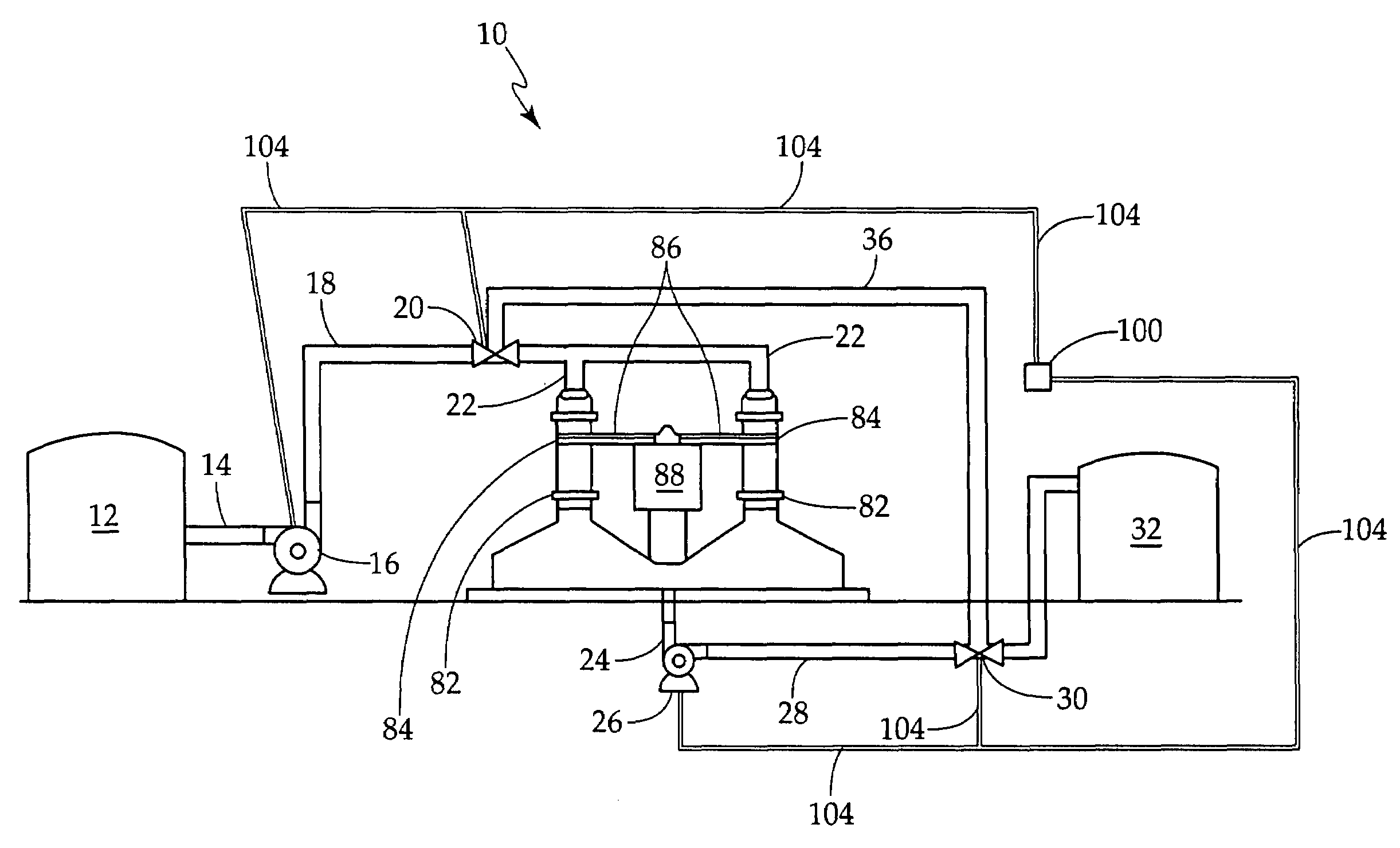
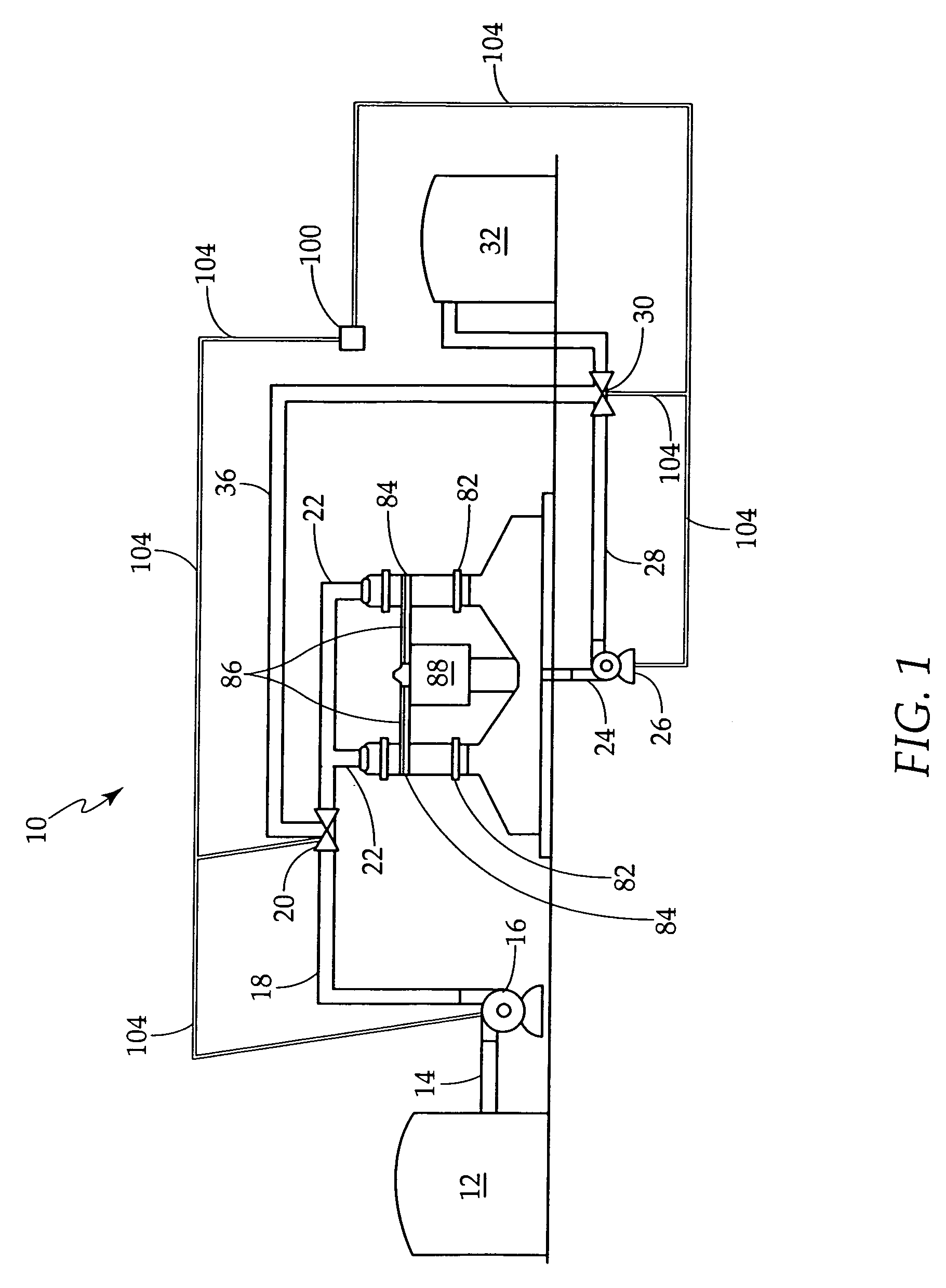
[0018]Referring now to FIG. 1, there is illustrated the comminution apparatus of the present invention generally indicated as 10, positioned within a system for treating a slurry of particulate material for particle size reduction. The system includes a storage tank 12 for the slurry of particulate material in fluid communication via a conduit 14 with the suction side of a pump 16. The discharge side of pump 16 is in fluid communication via a conduit 18, including a valve 20 to inlet conduits 22 of the comminution apparatus 10 as more fully hereinafter described. An outlet conduit 24 of the comminution apparatus 10 is in fluid communication with the suction side of a pump 26 with the discharge side thereof being in fluid communication via a conduit 28, including a valve member 30 to a product storage tank 32 for the product slurry of reduced particulate material. A recycle conduit 36 is in fluid communication between valves 20 and 30 to provide recycle requirements for the system.

[0...


PUM


Abstract

These and other objects of the present invention are achieved by a comminution apparatus comprised of a housing member formed with co-planar circularly-shaped chambers in chordal juxtaposition to each other thereby forming a collision zone therebetween and wherein wheel members having radially disposed directional vanes are positioned for rotation in each cylindrically-shaped chamber and wherein an inlet fluid conduit or a slurry of particulate matter to be treated is in axial fluid communication with each wheel member and wherein each wheel member is caused to be rotated in a direction to accelerate the slurry towards the collision zone and to affect particle size reduction by particle collision and wherein an outlet conduit is in fluid communication with the collision zone for withdrawing a slurry of size reduced particles from the comminution apparatus.

Description

Related Applications[0001]Applicant is the holder of U.S. Pat. No. 7,059,552, issued Jun. 3, 2006, entitled “Comminution Apparatus” to which the present application relates as an improved embodiment thereof.BACKGROUND OF THE INVENTION[0002]1. Field of the Invention[0003]The present invention relates to an apparatus for reduction of particle size, and more particularly to a comminution apparatus for uniformly disbursing solids within a liquid slurry to produce a homogeneous product.[0004]2. Description of the Prior Art[0005]A large number of manufacturing processes require for the uniform dispersion of dissimilar particulate materials to produce a homogeneous slurry product. Often, the starting particulate materials are irregular size, and must be reduced to a uniform size, such as a very fine powder, which are then uniformly dispersed within a solvent carrier to produce a master batch. This is particularly applicable in the arts of paints and printing inks.[0006]Some prior art devic...

Claims


Application Information

Patent Timeline
Patent Type & Authority Patents(United States)
IPC IPC(8): B02C1/10B02B1/00
CPCB02C13/20B02C19/0012
Inventor HAYLES, JR., PETER E.
Owner HAYLES JR PETER E
Why Eureka
Try Eureka