Electrochemical device such as electrochromic or photovoltaic device and electrical connection means thereof

a technology of electrochromic or photovoltaic devices and electrical connection means, which is applied in the direction of electrical equipment, fuel cells, sustainable buildings, etc., can solve the problems of reducing the “active” area and complicating the manufacture of the device, and achieves the effect of improving the connection and being simple and flexible to implemen

Inactive Publication Date: 2007-06-12
SAINT-GOBAIN GLASS FRANCE
View PDF15 Cites 147 Cited by
  • Summary
  • Abstract
  • Description
  • Claims
  • Application Information

AI Technical Summary

Benefits of technology

[0021]The aim of the invention is therefore to provide an improved connection for the electrically controllable systems of the glazing type which have been mentioned above. In particular, it has the aim of providing a connection which is better from a visual and / or electrical point of view and which, preferably, remains simple and flexible to implement on the industrial scale. It relates to all the systems listed above, and more specifically to the electrochromic glazing called “all-solid” glazing.

Problems solved by technology

This masking of the periphery of electrically controllable systems complicates their manufacture and moreover reduces the “active” area of the glazing that can be exploited by the user.

Method used


Image

  • Electrochemical device such as electrochromic or photovoltaic device and electrical connection means thereof
  • Electrochemical device such as electrochromic or photovoltaic device and electrical connection means thereof
  • Electrochemical device such as electrochromic or photovoltaic device and electrical connection means thereof

Examples


example 1

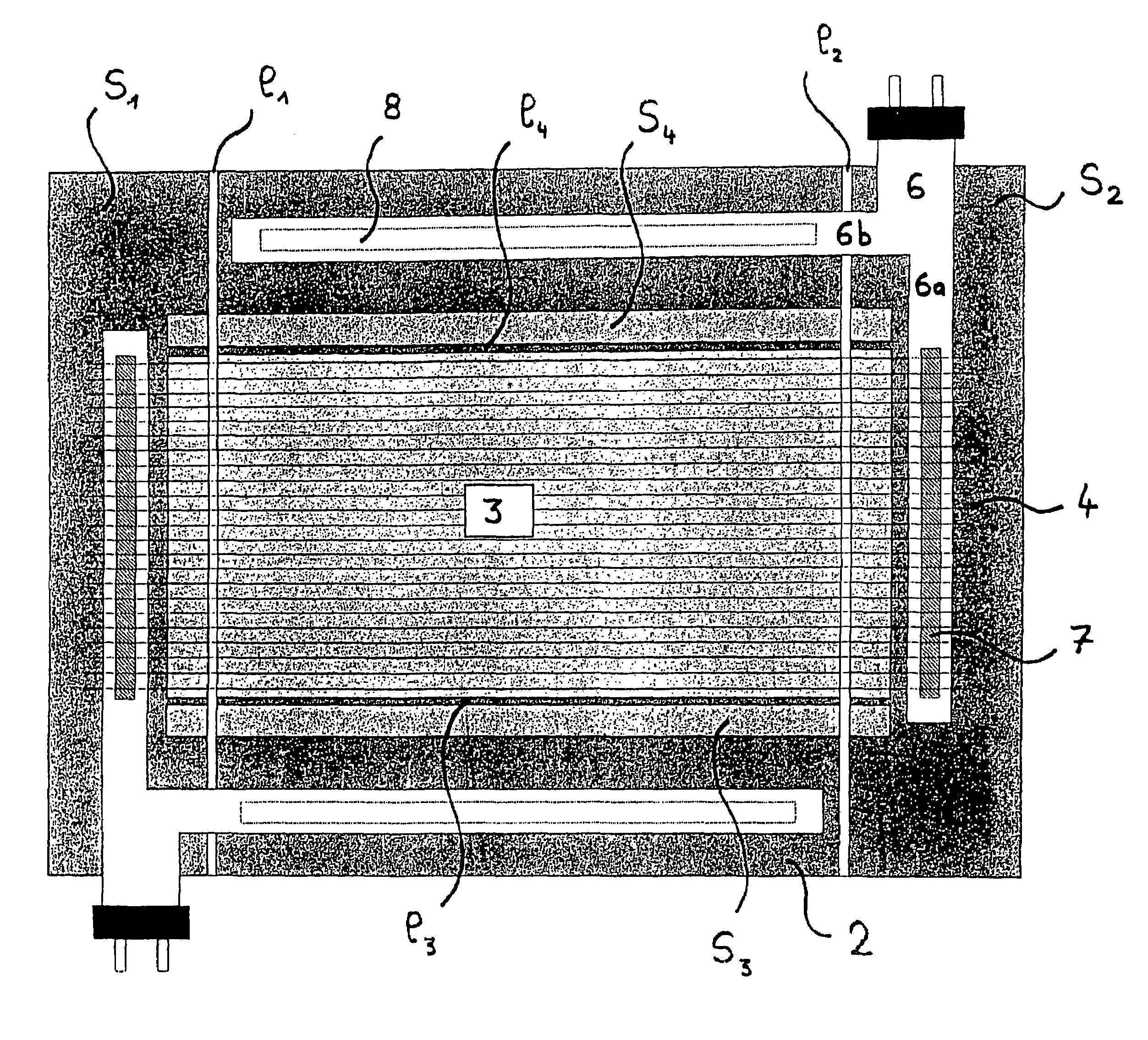
[0095]This is the configuration shown in FIG. 1:[0096]The lower conductive layer 2 covers the whole area of the glass pane. Its margins are set along two incision lines l1, l2 on its two smallest opposed sides (layer with overall rectangular shape), by means of a laser. The incision lines also affect the active system and the upper electrode since they are made after depositing all the layers. These two lines therefore delimit two regions s1 and s2 which are deactivated for the whole electrochromic system, including the two electrodes.[0097]The margins of the active system and the upper conductive layer 3 are also set along two other incision lines l3, l4, after depositing all the layers. These incisions do not affect the lower conductive layer, and are made on the longest edges of the system and of the upper conductive layer. The active system and the upper conductive layer also cover a rectangular region of the substrate, with dimensions less than those covered by the lower conduc...

example 2

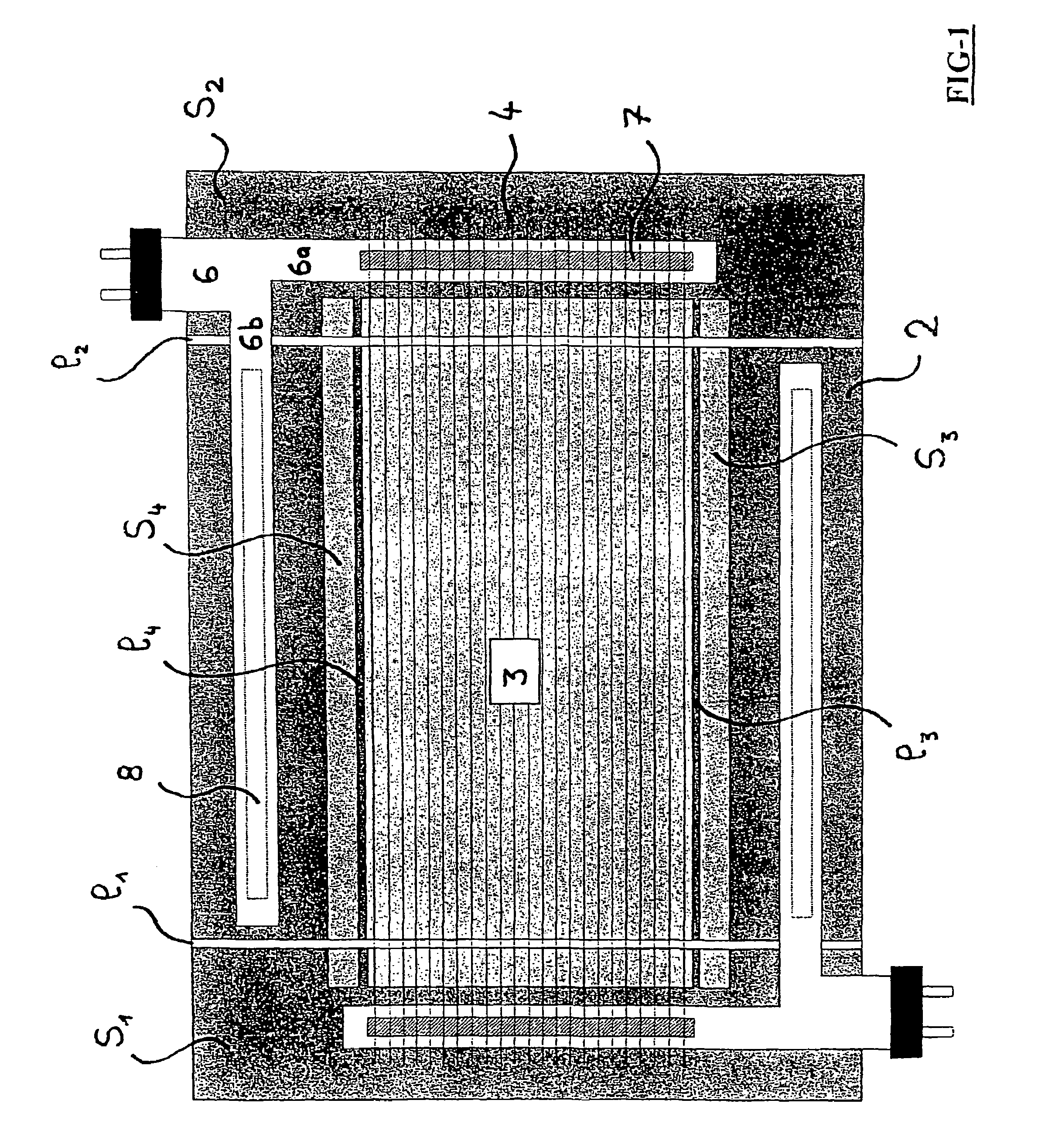
[0101]This is the configuration shown in FIG. 2 which is quite similar to that of example 1.

[0102]The difference with example 1 resides in the way in which the margins of the lower conductive layer 2 are set: in example 2, the incision is carried out along a closed line l5, which delimits an inactive region s5 over the entire periphery of the lower conductive layer, and over two opposed edges of the active system (as in the previous case).

example 3

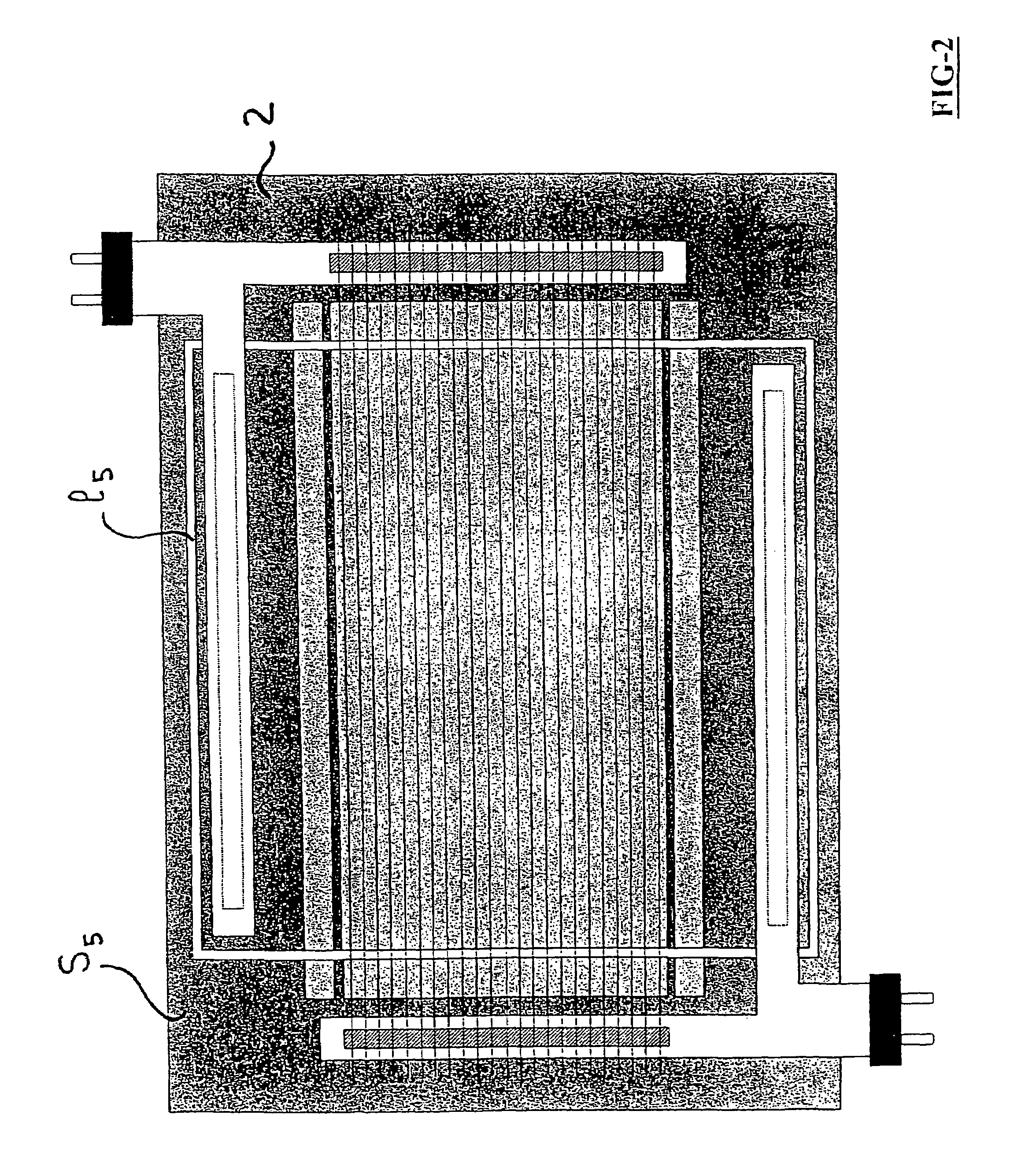
[0103]This is the configuration shown in FIG. 3 and which is a variant of the two preceding figures. This time, the margins of the lower conductive layer 2 are set along two closed lines l6, l7 which have a substantially rectangular outline, partly on the region covered by the conductive layer 2, partly on the region also covered by the active stack 3. As in Example 1, there are also two deactivated regions s6, s7 on the two opposed edges of the layer 2, delimited by the two lines l6 and l7, and which therefore do not go up to the extreme perimeter of the layer.

[0104]These three examples therefore have in common that they deactivate the electrochromic glazing on two of its opposed edges, in regions overlapping the region covered only by the lower conductive layer, and the region covered both by this layer and by the active stack 3.


PUM

PropertyMeasurementUnit
diameteraaaaaaaaaa
thickaaaaaaaaaa
thickaaaaaaaaaa

Abstract

An electrochemical device, especially an electrically controllable system with variable energy and/or optical properties or a photovoltaic device, including at least one substrate carrying an electroactive stack of layers arranged between a lower electrode and an upper electrode. Each electrode includes at least one electroconductive layer in electrical contact with at least one current lead. The current leads are arranged outside the region of the carrier substrate that is covered by the stack of electroactive layers.

Description

BACKGROUND OF THE INVENTION[0001]1. Field of the Invention[0002]The subject of the present invention is an electrochemical device, especially an electrically controllable system of the glazing type and with variable energy and / or optical properties or a photovoltaic device.[0003]2. Discussion of the Background[0004]At the present time, there is an increased demand for glazing called “intelligent” glazing capable of being adapted to the needs of the users.[0005]There is also an increased demand for photovoltaic glazing, which makes it possible to convert solar energy into electrical energy.[0006]With regard to “intelligent” glazing, this may involve controlling the amount of sun passing through glazing mounted externally in buildings or vehicles of the automobile, train or aircraft type. The aim is to enable excessive heating inside passenger compartments or premises to be limited, but only in the case of strong sunshine.[0007]It may also involve controlling the degree of vision thro...

Claims


Application Information

Patent Timeline
Patent Type & Authority Patents(United States)
IPC IPC(8): G02F1/15G02F1/153G02F1/155H01L31/04H01L31/05
CPCB32B17/10036B32B17/10174B32B17/10788B32B17/10376B32B17/10513G02F1/155G02F1/1533Y02B10/12B32B2457/12
Inventor GIRON, JEAN-CHRISTOPHEBETEILLE, FABIENFANTON, XAVIERCLAUDE, LAURENTDUBRENAT, SAMUEL
Owner SAINT-GOBAIN GLASS FRANCE
Why Eureka
Try Eureka