Electrophoretic displays using gaseous fluids

a technology of electrophoretic displays and fluids, applied in the field of electrophoretic displays using gaseous fluids, can solve the problems of inadequate service life of these displays, widespread use, and the inability to meet the needs of the user, and achieve the effect of reducing the transmission of ultraviolet radiation

Active Publication Date: 2007-06-12
E INK CORPORATION
View PDF225 Cites 321 Cited by
  • Summary
  • Abstract
  • Description
  • Claims
  • Application Information

AI Technical Summary

Benefits of technology

[0027]In another aspect, this invention provides an electrophoretic display comprising a pair of facing substrates at least one of which is transparent, a plurality of particles and a gas enclosed between the substrates, and means for applying an electric field across the substrates so as to cause the particles to move between the substrates, wherein the transparent substrate is provided with a coating for reducing the transmission of ultraviolet radiation through the transparent substrate. This type of display may hereinafter be called a “UV coated display” of the present invention. The coating may comprise, for example, a polymeric film or a sputtered coating.

Problems solved by technology

Nevertheless, problems with the long-term image quality of electrophoretic displays have prevented their widespread usage.
For example, particles that make up electrophoretic displays tend to settle, resulting in inadequate service-life for these displays.
Such gas-based (“GB”) electrophoretic media appear to be susceptible to the same types of problems due to particle settling as liquid-based electrophoretic media, when the media are used in an orientation which permits such settling, for example in a sign where the medium is disposed in a vertical plane.
Indeed, particle settling appears to be a more serious problem in gas-based electrophoretic media than in liquid-based ones, since the lower viscosity of gaseous fluids as compared with liquid ones allows more rapid settling of the electrophoretic particles.

Method used


Image

  • Electrophoretic displays using gaseous fluids
  • Electrophoretic displays using gaseous fluids

Examples


Embodiment Construction

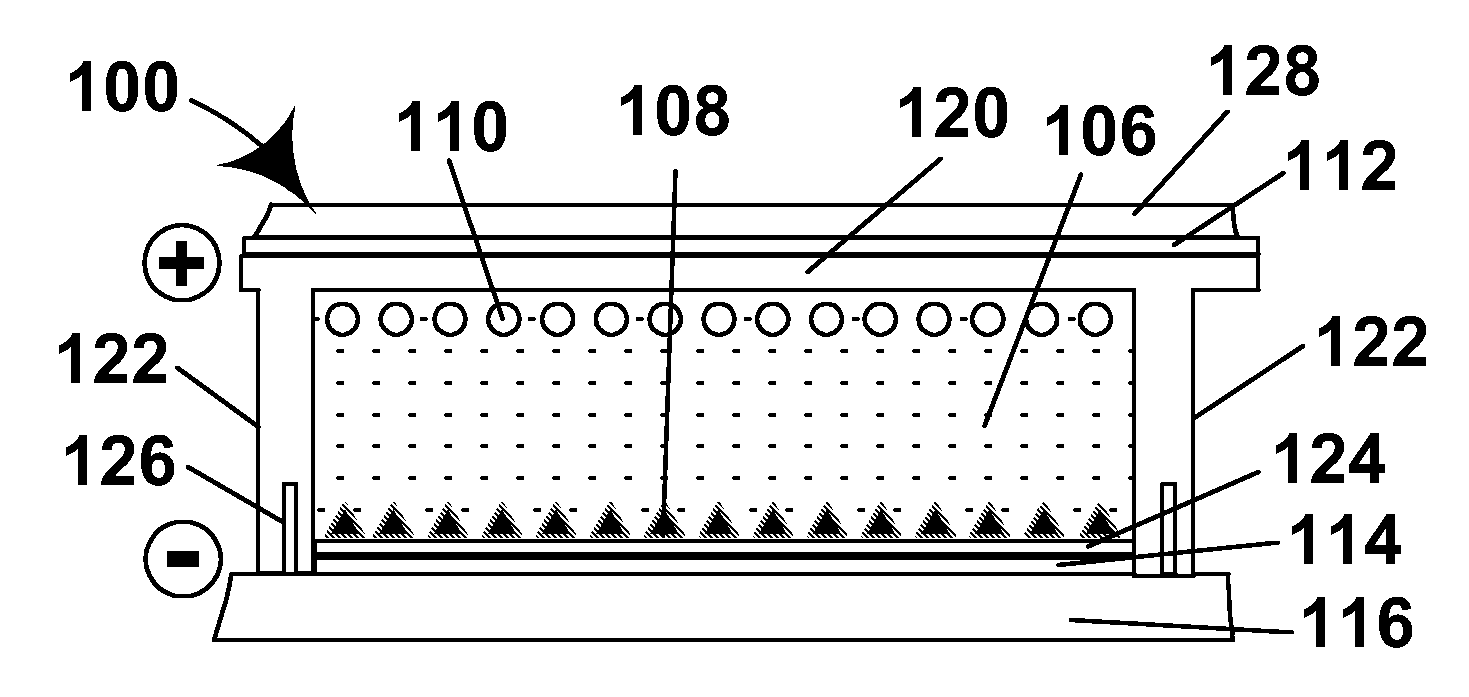
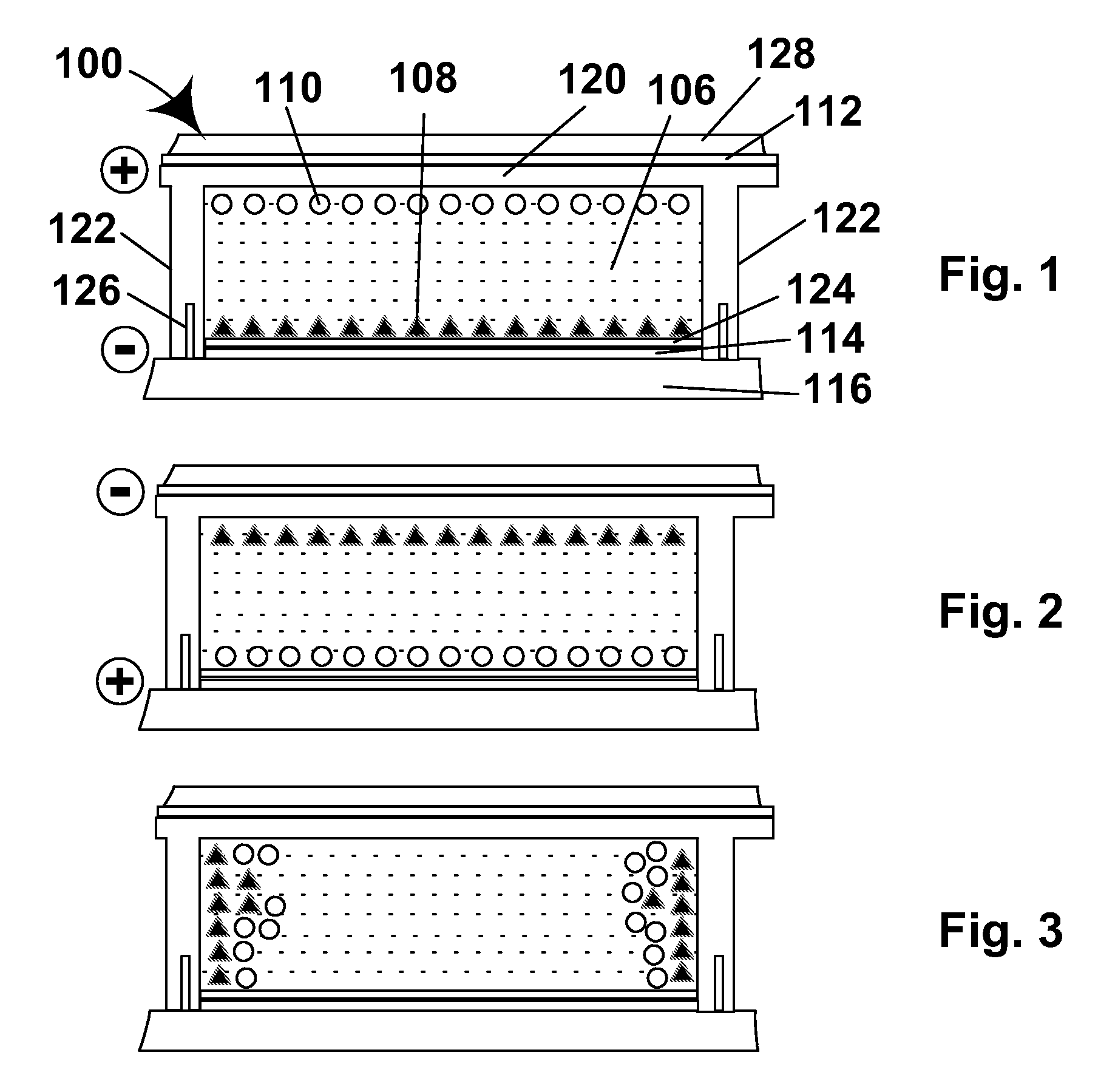
[0044]As will be apparent from the foregoing Summary of the invention Section, this invention provides numerous different improvements in gas-based electrophoretic displays. The various aspects of the invention will mainly be described separately below, but it should be recognized that a single gas-based electrophoretic display may make use of several different aspects of the invention. For example, the accompanying drawings are provided primarily to illustrate the operation of a lateral movement display of the present invention, but the illustrated display could also make use of coated titania particles, coated carbon black particles, walls with controlled resistivity or other aspects of the present invention.

[0045]Improvements Relating to Charging of Gas-Based Displays

[0046]The first major problem with GB electrophoretic displays relates to developing and maintaining charge on the electrophoretic particles. Obviously, the electrophoretic movement of particles for changing the opti...


PUM

PropertyMeasurementUnit
volume resistivityaaaaaaaaaa
glass transition temperatureaaaaaaaaaa
frequencyaaaaaaaaaa

Abstract

Various improvements are provided in gas-based electrophoretic displays, including (a) the use of water getters to remove water from the gas; (b) the use of electron accepting or donating gases; (c) the use of electrophoretic polymer particles having high glass transition temperatures; (d) lateral movement of electrophoretic particles within the display; and (e) the use of variable thickness coatings on electrodes to provide for gray scale.

Description

REFERENCE TO RELATED APPLICATION[0001]This application claims benefit of Provisional Application Ser. No. 60 / 593,570, filed Jan. 26, 2005, and Provisional Application Ser. No. 60 / 593,674, file Feb. 4, 2005. The entire contents of these copending applications, and of all other U.S. patents and published and copending applications mentioned below, are herein incorporated by reference.BACKGROUND OF INVENTION[0002]This invention relates to electrophoretic displays using gaseous fluids.[0003]Particle-based electrophoretic displays, in which a plurality of charged particles move through a fluid under the influence of an electric field so as to change at least one optical property or optical characteristic of the display, have been the subject of intense research and development for a number of years. Such displays can have attributes of good brightness and contrast, wide viewing angles, state bistability, and low power consumption when compared with liquid crystal displays. Although the o...

Claims


Application Information

Patent Timeline
Patent Type & Authority Patents(United States)
IPC IPC(8): G02B26/00G09G3/34G02F1/1671G02F1/1676
CPCG02F1/167G02F1/1671G02F1/1676G02F1/133311
Inventor WHITESIDES, THOMAS H.DANNER, GUY M.AMUNDSON, KARL R.HONEYMAN, CHARLES HOWIEWILCOX, RUSSELL J.MCCREARY, MICHAEL D.
Owner E INK CORPORATION
Why Eureka
Try Eureka