Method and circuit for cascaded pulse width modulation

a cascaded pulse width and modulation technology, applied in pulse manipulation, pulse technique, instruments, etc., can solve the problems of complex control design, difficult design of compensators for each individual loop, and high cost, so as to eliminate dc-capacitor voltage imbalan

Inactive Publication Date: 2007-06-12
ELECTRIC POWER RES INST INC +2
View PDF7 Cites 84 Cited by
  • Summary
  • Abstract
  • Description
  • Claims
  • Application Information

AI Technical Summary

Benefits of technology

[0015]According to another embodiment of the invention, a method of balancing the voltage of DC links in a cascaded multi-level converter (CMC) semiconductor circuit, comprising the steps of providing a plurality of H-bridge converters in the CMC circuit, and utilizing a three phase command multilevel duty cycle value from the main controller to determine a normalized duty cycle value, a ceiling duty cycle value and a floor duty cycle value. The normalized duty cycle value and an output current of the CMC are utilized to determine the direction and polarity of the normalized duty cycle value and a capacitor current, and the capacitor current is used to determine a plurality of output capacitor voltages. The capacitor voltages are sorted to obtain a register containing a plurality of indices representing sorted capacitor voltages, and the multi-level duty cycle voltage, the direction and polarity of the duty cycle output voltage and the sorted capacitor voltages are input into an index generator. A ceiling index pointer and a floor index pointer calculated, wherein the ceiling index pointer corresponds to an input ceiling duty cycle representing a number of the plurality of H-bridge converters required to generate a positive output voltage, and the floor index pointer corresponds to an input floor duty cycle representing a number of the plurality of H-bridge converters required to generate a negative output voltage. A voltage summation result and direction are determined from the ceiling index pointer and a floor index pointer and used to create a combined switching table for the H-bridge converters. The pulse width modulator is used to balance the voltage of the DC links and thereby eliminate DC-capacitor voltage imbalance.
[0016]A circuit for balancing the voltage of DC links in a cascaded multi-level converter (CMC) comprises plurality of H-bridge converters, a main controller for utilizing a three phase duty cycle value to determine a normalized duty cycle value, a ceiling duty cycle value and a floor duty cycle value, and a direction and duty cycle check circuit utilizing the normalized duty cycle value and an output current of the CMC to determine the direction and polarity of a capacitor current, and utilizing the capacitor current to determine a plurality of output capacitor voltages. A sorting network circuit is provided for sorting the capacitor voltages to obtain a register representing sorted capacitor voltages. An index generator is provided for receiving the multi-level duty cycle voltage, the polarity of the duty cycle output voltage and the sorted capacitor voltages and calculating a ceiling index pointer and a floor index pointer wherein the ceiling index pointer corresponds to an input ceiling duty cycle representing a number of the plurality of H-bridge converters required to generate a positive output voltage, and the floor index pointer corresponds to an input floor duty cycle representing a number of the plurality of H-bridge converters required to generate a negative output voltage, determining therefrom a voltage summation result and direction from the ceiling index pointer and a floor index pointer, and utilizing the voltage summation result, direction from the ceiling index pointer and a floor index pointer to create a combined switching table for the H-bridge converters. A pulse width modulator is utilized to balance the voltage of the DC links and thereby eliminate DC-capacitor voltage imbalance.

Problems solved by technology

The compensators of each individual loop, however, are very difficult to design because of the complexity of the voltage-loop transfer functions.
This process is very time-consuming.
Moreover, the greater the number of voltage levels, the more complex the control design.
As a result, the prior art approach potentially reduces the reliability of the controller.

Method used


Image

  • Method and circuit for cascaded pulse width modulation
  • Method and circuit for cascaded pulse width modulation
  • Method and circuit for cascaded pulse width modulation

Examples


example 1

[0068]A general PWM waveform synthesized by the proposed PWM, as shown in FIG. 14, is described and explained by way of example. In the period between T and 1.5T s, the duty cycle {right arrow over (D)}A—T is read. The switching signals corresponding to the index JF are sent to the main switches. At the moment that the negative slope slp1 intersects {right arrow over (D)}A—T, the main switches are switched to the switching signals corresponding to the index Jc. In the second half-cycle, the duty cycle is updated to {right arrow over (D)}A—0.5T. The status of the main switches is, however, still unchanged. Until the moment at which the positive slope slp2 intersects {right arrow over (D)}A—0.5T, the main switches are switched back to the switching signals corresponding to the index JF. This completes a switching cycle.

[0069]To illustrate the performance of the cascaded PWM technique, a single-phase, seven-level cascaded-based STATCOM with the DSP-based controller is set up and tested...

example 2

DC Voltage-Balancing During Transient

[0070]In this experiment, the STATCOM operates in the worst-case transient, which is either from the full capacitive to full inductive mode or vice versa. From the experimental results as shown in FIG. 15. At time t1 the STATCOM is commanded to abruptly transfer from the full inductive to the full capacitive mode. Before time t1, the output current iA, which is leading the voltage at the PCC, VpccA, by 90°, indicates that the STATCOM operates in the inductive mode, while the output current iA lagging VpccA by 90° after time t1 indicates that the STATCOM operates in the capacitive mode. The result shows the fast response of iA to the step command. During the full capacitive mode, the 120 Hz voltage ripple across the DC capacitor is at its maximum, which is approximately 7 Vpeak-to-peak or 10% of the DC voltage setting of 70 V, and which is consistent with the EA1 waveform, as shown in FIG. 15. Since three H-bridge converters are used in one phase ...

example 3

DC Voltage-Balancing During Capacitor Disturbation

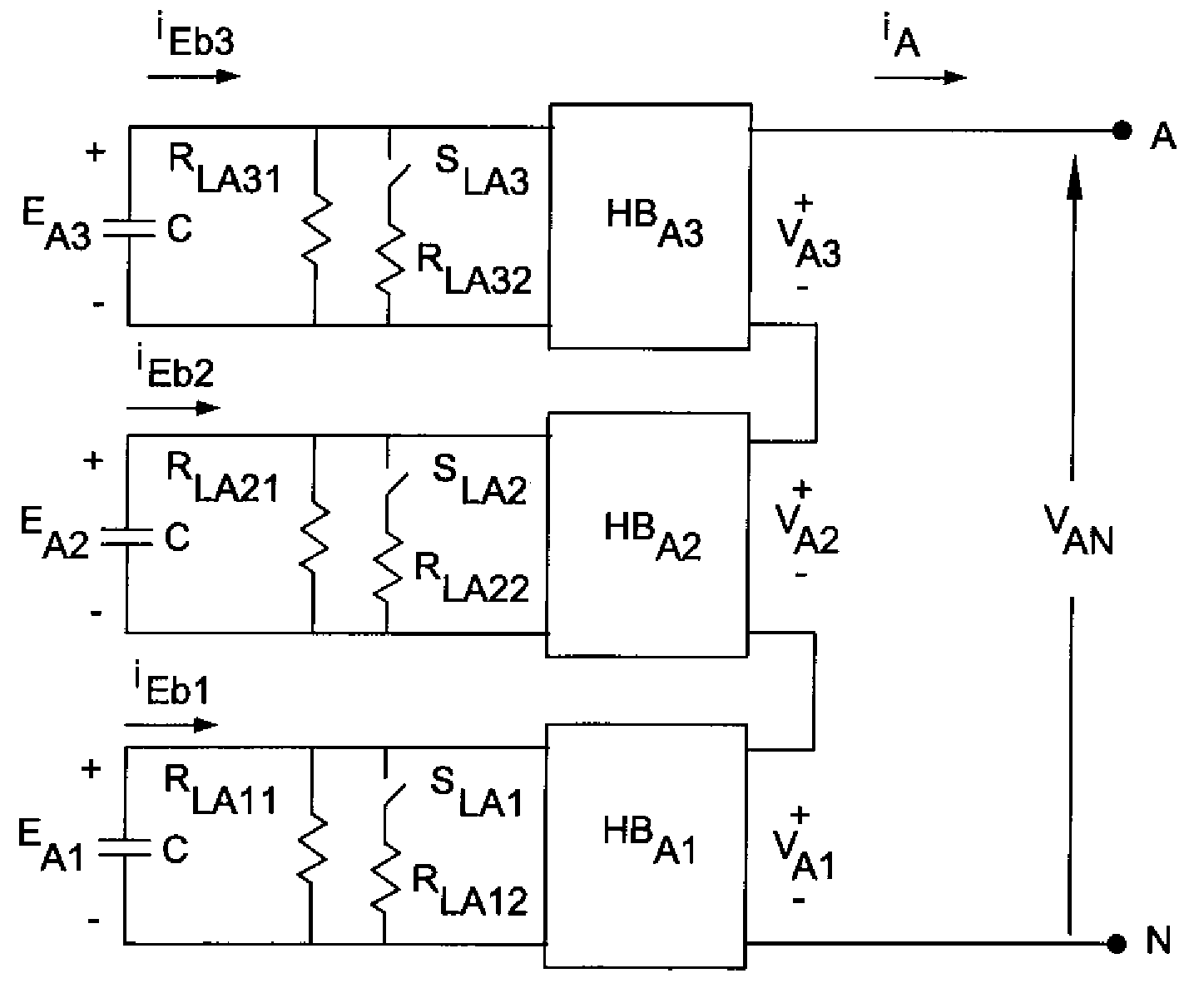
[0072]To further verify the performance of the proposed cascaded PWM technique, phase A of the seven-level cascaded converter is set up as shown in FIG. 17. A set of resistors is paralleled with the DC capacitors and represent the additional losses of the H-bridge converters. The semiconductor switches SLA1 through SLA3 are used to control the resistance across the DC capacitors. With the combination of these three switches, several different resistances across the DC capacitors can be effected during different STATCOM operation modes.

[0073]In the first case, the full-capacitive mode, the losses of all three H-bridge converters are increased by connecting three different resistors in parallel with Hie DC-bus capacitors. The response of the three DC capacitors voltages, EA1 through EA3, to the disturbance at the DC links is shown in FIG. 18. The rising edge of the SLA1 gate signal indicates the beginning of the DC-capacitor voltage di...


PUM


Abstract

A method of balancing the voltage of DC links in a cascaded multi-level converter (CMC) semiconductor circuit, including the steps of providing a plurality of H-bridge converters per phase in the CMC circuit and utilizing a three phase duty cycle value from the main controller to determine a normalized duty cycle value, a ceiling duty cycle value and a floor duty cycle value. The normalized duty cycle value and an output current of the CMC is used to determine the direction and polarity of a capacitor current, and utilizing the capacitor current to determine a plurality of output capacitor voltages. A voltage summation result and direction is obtained from a ceiling index pointer and a floor index pointer and the voltage summation result, direction from the ceiling index pointer and a floor index pointer are used to create a combined switching table for the H-bridge converters. A pulse width modulator is utilized to balance the voltage of the DC links and thereby eliminate DC-capacitor voltage imbalance.

Description

TECHNICAL FIELD AND BACKGROUND OF THE INVENTION[0001]The present invention generally relates to the field of power electronics, and more particularly to a novel pulse width modulation (PWM) technique and circuit for balancing the voltage of DC links of a cascaded-multilevel converter (CMC) for reactive power compensations. The invention has application in, for example, electric power generation in Flexible Alternating Current Transmission systems (FACTS) and motor drives, and is useful in both active and reactive power generation.[0002]The method and circuit described and claimed in this application can be implemented by hardware circuitry. Thus, the calculation time in the digital signal processor (DSP) is only slightly increased as more voltage levels are employed. The basic structure of the proposed technique is modular. Therefore, the method and circuit may be employed for any number of H-bridge converters. With these features, the complexity of the DSP programming for the contr...

Claims


Application Information

Patent Timeline
Patent Type & Authority Patents(United States)
IPC IPC(8): H02M7/521H02J1/14
CPCH02J3/1857H02M7/49H02M7/5395Y02E40/26H02M2007/4835Y02E40/20H02M7/4835
Inventor HUANG, QINEDRIS, ABDEL-ATYINGRAM, MICHAEL R.SIRISUKPRASERT, SIRIROJ
Owner ELECTRIC POWER RES INST INC
Why Eureka
Try Eureka