High temperature spiral snake superconducting resonator having wider runs with higher current density
What is Al technical title?
Al technical title is built by PatSnap Al team. It summarizes the technical point description of the patent document.
a superconducting resonator and high temperature technology, applied in the direction of superconducting magnets/coils, superconductor devices, magnetic bodies, etc., can solve the problems of large circuit to circuit differences, filter over a foot in length, and rods can become quite large, so as to reduce intermodulation effects and reduce peak current densities
Inactive Publication Date: 2007-06-12
SUPERCONDUCTOR TECHNOLOGIES INC
View PDF91 Cites 4 Cited by
Summary
Abstract
Description
Claims
Application Information
AI Technical Summary
This helps you quickly interpret patents by identifying the three key elements:
Problems solved by technology
Method used
Benefits of technology
[0015]Accordingly, it is an object of this invention to provide improved high temperature superconducting structures.
[0018]It is yet a further object of this invention to provide high Q, superconducting resonators having reduced intermodulation effects.
Problems solved by technology
However, the use of separate elements has proved to be difficult in manufacture, and resulting in large circuit to circuit differences.
Accordingly, the bars or rods can become quite sizeable, often being several inches long, resulting in filters over a foot in length.
Again, the size of these filters can become quite large.
These materials have an inherent loss, and as a result, the circuits have various degree of lossiness.
For resonant circuits, the loss is particularly critical.
The need for compact, reliable narrow band filters has never been stronger.
As described, such structures are often smaller than conventional technologies in terms of physical size.
However, these devices are also limited in their size given the constraints of fabricating high quality, epitaxial films.
This often results in folding of devices, which leads to significant coupling between lines.
Despite the clear desirability of improved electrical circuits, including the known desirability of converting circuitry to include superconducting elements, efforts to date have been less than satisfactory in all regards.
It has proved to be especially difficult in substituting high temperature superconducting materials to form circuits without severely degrading the intrinsic Q of the superconducting film.
These problems include circuit structure, radiative loss and tuning and have remained in spite of the clear desirability of an improved circuit.
Method used
Image
Click on the blue label to locate the original text in one second.
Reading with bidirectional positioning of images and text.
Examples
Embodiment Construction
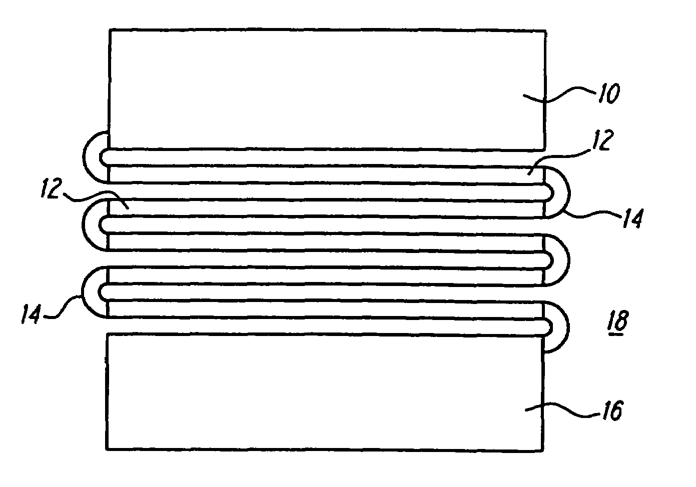
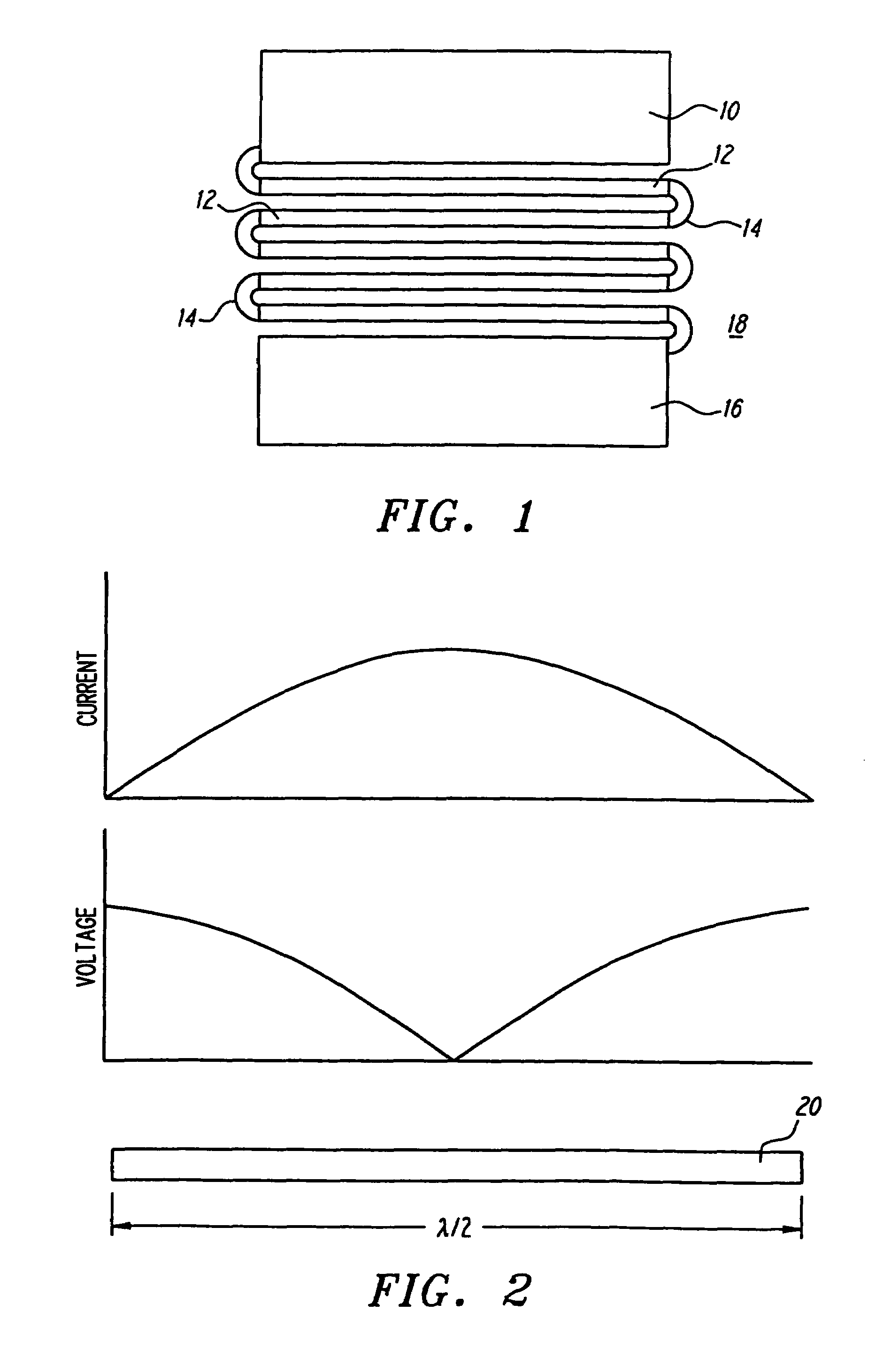
[0048]FIG. 1 shows a plan view of a quasi-lumped element resonator (QLE) having enlarged input and output pads. An input pad 10 (the designation of input and output being arbitrary, and reversible) and an output pad 16 are disposed on opposite sides of a serpentine or zig-zag resonator region 18. Generally parallel long runs 12 are disposed substantially parallel to the longer edge of the input pad 10 and output pad 16. A first long run 12 adjacent to the input pad 10 is connected to a first turn 14 which electrically couples the input pad 10 to the first long run 12. Adjacent long runs 12 are then coupled to their nearest neighbor long runs 12 by corresponding turns 14.
[0049]The input pads 10 and output pad 16 serve to increase the equivalent capacitance to ground relative to a structure having no or smaller input and output pads. Preferably, the amount of equivalent capacitance to ground is selected in accordance with the electrical requirements of the circuit. As shown in FIG. 1,...
PUM
Property
Measurement
Unit
total width
aaaaa
aaaaa
frequency
aaaaa
aaaaa
width
aaaaa
aaaaa
Abstract
Novel structures and methods for forming useful high temperature superconducting devices, most particularly resonators, are provided. Structures resulting in reduced peak current densities relative to known structures achieve numerous desirable benefits, especially including the reduced intermodulation effects of earlier resonators. In one aspect of this invention, a spiral in, spiral out resonator is provided, characterized in that it has an odd number of long runs, at least equal to five long runs, where the long runs are connected by turns, and wherein there are at least two sequential turns of the same handedness, followed by at least two turns of the opposite handedness. In yet another aspect of this invention, it has been discovered that reducing the size of the input and output pads of HTS resonators increases the relative inductance compared to the capacitance. Yet another resonator structure is a spiral snake resonator having a terminal end disposed within the resonator. A wide in the middle structure and wide at peak current density resonator structures utilize enlarged width portions of the resonator in those areas where current density is largest. In yet another aspect of this invention, operation of resonators in high modes, above the fundamental mode, reduce peak current densities. Resonators operated in modes in which current in adjacent long runs are in the same direction further serve to reduce current densities, and intermodulation effects. Symmetric current structures and modes of operation are particularly advantageous where far field effects are compensated for.
Description
RELATED APPLICATION[0001]This application is a continuation of application Ser. No. 10 / 167,938, filed Jun. 10, 2002, now issued as U.S. Pat. No. 6,895,262 which is a continuation of application Ser. No. 09 / 460,274, filed Dec. 13, 1999, now issued as U.S. Pat. No. 6,424,846, which is a continuation of application Ser. No. 08 / 885,473, filed on Jun. 30, 1997, issued as U.S. Pat. No. 6,026,311, which is a continuation-in-part of application Ser. No. 08 / 826,435 (224 / 302), filed Mar. 20, 1997, now abandoned, which is a continuation of application Ser. No. 08 / 297,289, filed Aug. 26, 1994, entitled “Lumped Element Filters”, issued as U.S. Pat. No. 5,616,539, which is in turn a continuation-in-part of application Ser. No. 08 / 070,100 filed May 28, 1993, entitled “Lumped High Temperature Superconductor Lumped Elements and Circuits Therefrom” (as amended), issued as U.S. Pat. No. 5,618,777 on Apr. 8, 1997.FIELD OF THE INVENTION[0002]This invention relates to structures and methods formed from h...
Claims
Application Information
Patent Timeline
Application Date:The date an application was filed.
Publication Date:The date a patent or application was officially published.
First Publication Date:The earliest publication date of a patent with the same application number.
Issue Date:Publication date of the patent grant document.
PCT Entry Date:The Entry date of PCT National Phase.
Estimated Expiry Date:The statutory expiry date of a patent right according to the Patent Law, and it is the longest term of protection that the patent right can achieve without the termination of the patent right due to other reasons(Term extension factor has been taken into account ).
Invalid Date:Actual expiry date is based on effective date or publication date of legal transaction data of invalid patent.