Medical diagnostic ultrasound catheter with dielectric isolation

a technology of ultrasound catheter and dielectric isolation, which is applied in the field of medical diagnostic ultrasound catheter, can solve the problems of cost prohibitive, large thickness, and waste of production, and achieve the effects of reducing capacitive coupling effect, improving dielectric withstand strength, and reducing the risk of defective manufactur

Inactive Publication Date: 2007-06-19
SIEMENS MEDICAL SOLUTIONS USA INC
View PDF41 Cites 26 Cited by
  • Summary
  • Abstract
  • Description
  • Claims
  • Application Information

AI Technical Summary

Benefits of technology

[0007]The present invention is defined by the following claims, and nothing in this section should be taken as a limitation on those claims. By way of introduction, the preferred embodiment described below includes a medical diagnostic ultrasound catheter with materials for improved dielectric withstand strength. In one aspect, the catheter includes a braid of non-conductive material. The non-conductive braid reduces the capacitive coupling effects and allows smaller catheters or a greater number of conductors. The non-conductive braid provides both compressive and tensile strength to transmit the torque applied to the catheter. The non-conductive braid also allows fusing of components while decreasing the risk of defective manufacture.
[0008]In another aspect, a dielectric film, such as a polyester film, is positioned between the transducer and any lens or window. The dielectric film allows thinner lenses to be used, allowing smaller catheters or larger transducers. The dielectric film may also increase the sensitivity of the transducer to acoustic energy. The dielectric film prevents the lens material from filling kerfs in the transducer, which may eliminate the need for filling the kerfs of the transducer.

Problems solved by technology

A fused catheter more likely will not pass the safety requirements due to migration of the metal braid, resulting in wasted production.
However, the required thickness may be considerable.
Isolating each conductor with a transformer is cost prohibitive.

Method used


Image

  • Medical diagnostic ultrasound catheter with dielectric isolation
  • Medical diagnostic ultrasound catheter with dielectric isolation

Examples


Embodiment Construction

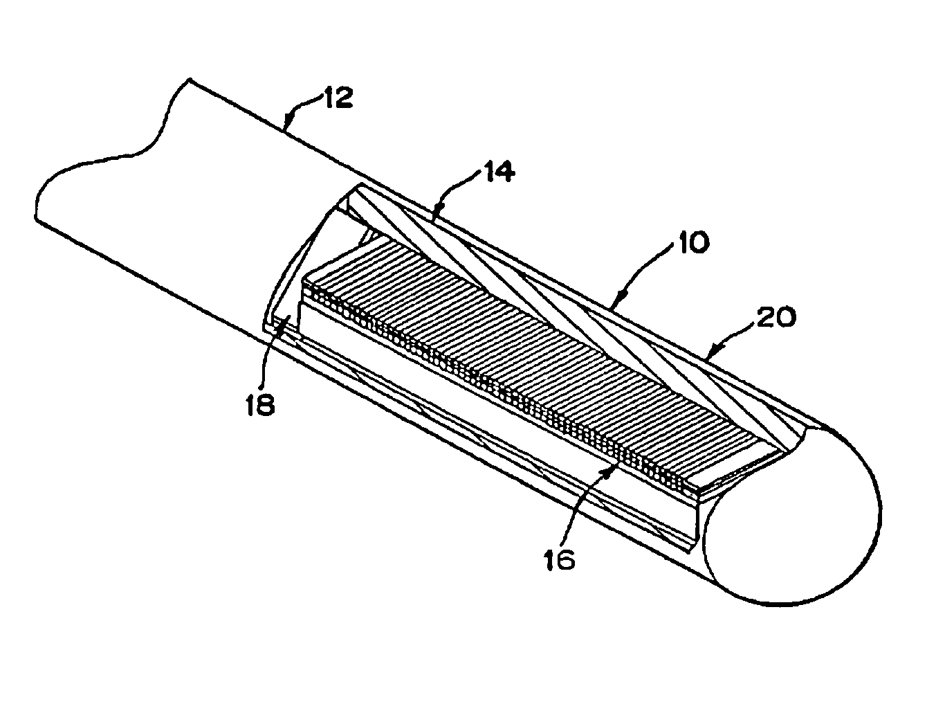
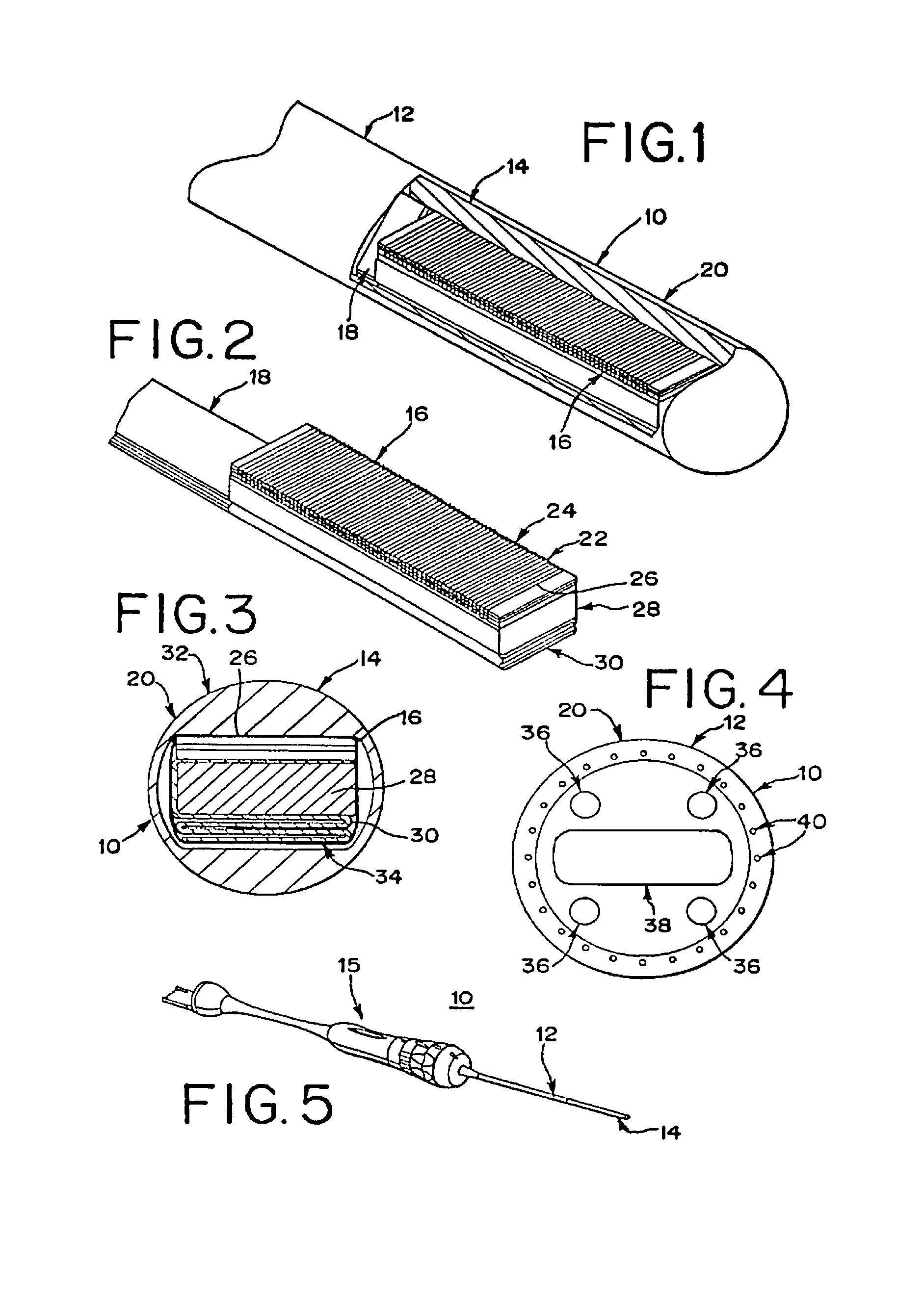
[0017]The preferred embodiments of the medical diagnostic ultrasound catheter include one or both of (1) a non-conductive insert for providing torque transmission and (2) a dielectric film extending around at least a portion of a transducer. The non-conductive insert described below prevents or reduces capacitive coupling, allowing for thinner catheter walls. The dielectric film described below allows for less thick lenses adjacent to the transducer while still providing sufficient dielectric withstand for the 3,000 volts safety requirement.

[0018]Referring to FIGS. 1 and 5, a medical diagnostic ultrasound catheter is generally shown at 10. The catheter 10 includes a body portion 12 and a tip portion 14. A handle and control portion 15 (FIG. 5) connects with the body portion 12. The tip portion 14 includes a transducer 16 and associated conductors 18. The conductors also pass through the body portion 12. The catheter 10, including the body portion 12 and tip portion 14, comprises a s...


PUM


Abstract

Medical diagnostic ultrasound catheters are provided with improved materials for dielectric withstand strength. In one aspect, the catheter includes a braid of non-conductive material. The non-conductive braid reduces the capacitive: coupling effects and allows smaller catheters or a greater number of conductors. The non-conductive braid provides both compressive and tensile strength to transmit the torque applied to the catheter. The non-conductive braid also allows fusing of components while decreasing the risk of defective manufacture. In another aspect, a dielectric film, such as a polyester film, is positioned between the transducer and any lens or window. The dielectric film allows thinner window lenses to be used, allowing smaller catheters or larger transducers. The dielectric film may also increase the sensitivity of the transducer to acoustic energy. The dielectric film prevents the lens or window material from filling kerfs in the transducer, which may eliminate the need for filling the kerfs of the transducer.

Description

BACKGROUND[0001]This invention relates to medical diagnostic ultrasound catheters. In particular, different materials for constructing medical diagnostic ultrasound catheters provide improvements in dielectric isolation.[0002]Catheters for use with ultrasound systems include transducers for converting electrical energy to acoustic energy and vice versa. Images of a region of a patient adjacent to the transducer are generated. In order to provide accurate imaging, a window or lens is integrated with the catheter adjacent to the transducer. The remainder of the exterior of the catheter generally comprises polyurethane or other biologically acceptable material. In order to provide torque transmission and flexibility, an internal metal braid is provided.[0003]For safe inter-cardiac use of a catheter, the catheter must dielectrically withstand 3,000 volts for 60 seconds between the external surface of the catheter and any internal conductors or electrically active components when interna...

Claims


Application Information

Patent Timeline
Patent Type & Authority Patents(United States)
IPC IPC(8): A61M25/00A61B8/14A61B8/00
CPCA61B8/12A61B8/445A61M25/0032A61M25/005A61M2025/0034A61M2025/0036
Inventor SCHLESINGER, RANDALL L.RAHIMI, MATHEW
Owner SIEMENS MEDICAL SOLUTIONS USA INC
Why Eureka
Try Eureka