Fuel cell

Active Publication Date: 2007-06-19
HONDA MOTOR CO LTD
View PDF4 Cites 7 Cited by
  • Summary
  • Abstract
  • Description
  • Claims
  • Application Information

AI Technical Summary

Benefits of technology

[0019]A main object of the present invention is to provide a compact and light fuel cell having thin separators without using any belleville springs.
[0023]The spring mechanism maintains the tightening force for tightening the entire fuel cell stack substantially uniformly. Therefore, it is not necessary to use any belleville springs at an end of the fuel cell stack in the stacking direction. Further, it is not necessary to use any dedicated leaf springs or the like in the fuel cell stack. Since the metal plates are used as the separators, the separators are thin in contrast to the conventional separators made of carbon. Therefore, the overall fuel cell is compact and light.

Problems solved by technology

Therefore, a relatively large space is needed for installing the fuel cell stack 10.
Therefore, the overall fuel cell stack 10 is relatively large and heavy.

Method used


Image

  • Fuel cell
  • Fuel cell
  • Fuel cell

Examples


Embodiment Construction

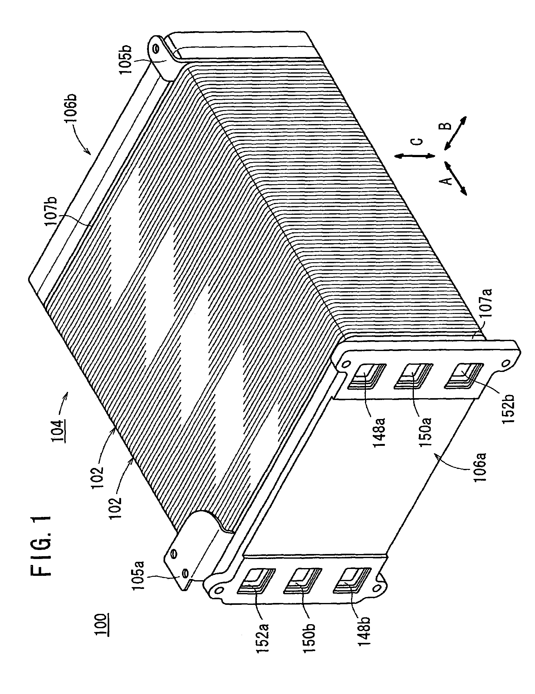
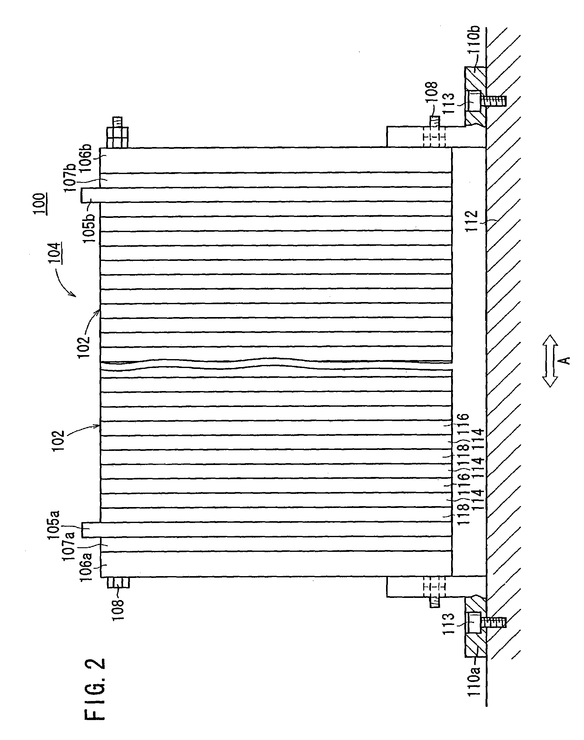
[0036]FIG. 1 is a schematic perspective view showing a fuel cell stack 100 formed by stacking a plurality of fuel cells according to an embodiment of the present invention. FIG. 2 is a cross sectional side view showing a part of the fuel cell stack 100.

[0037]The fuel cell stack 100 includes a stack body 104 formed by stacking a plurality of fuel cells (unit cells) in a stacking direction indicated by an arrow A. A positive electrode terminal 105a and a negative electrode terminal 105b are connected to outermost unit cells disposed at opposite ends of the stack body 104 in the stacking direction, respectively. Insulator plates 107a, 107b for prevention of electric leakage are stacked on the outside of the positive electrode terminal 105a, and the negative electrode terminal 105b, respectively. Further, end plates 106a, 106b are stacked on the outside of the insulator plates 107a, 107b, respectively.

[0038]As shown in FIG. 2, end plates 106a, 106b are tightened by a tightening mechanis...


PUM


Abstract

First and second separators include first and second metal plates. The first metal plate has first embossed protrusions protruding toward a membrane electrode assembly to form an oxygen-containing gas flow passage. The second metal plate has second embossed protrusions protruding toward another membrane electrode assembly to form a fuel gas flow passage. Further, the second metal plate has third small embossed protrusions protruding toward the first metal plate.

Description

BACKGROUND OF THE INVENTION[0001]1. Field of the Invention[0002]The present invention relates to a fuel cell including an electrolyte electrode assembly and a pair of separators. The electrolyte electrode assembly includes an anode, a cathode, and an electrolyte interposed between the anode and the cathode. The electrolyte electrode assembly is interposed between the separators.[0003]2. Description of the Related Art[0004]For example, a solid polymer electrolyte fuel cell employs a membrane electrode assembly (MEA) which comprises two electrodes (anode and cathode) and an electrolyte membrane interposed between the electrodes. The electrolyte membrane is a polymer ion exchange membrane (proton exchange membrane). Each of the electrodes comprises a catalyst and a porous carbon sheet. The membrane electrode assembly is interposed between separators (bipolar plates). The membrane electrode assembly and the separators make up a unit of the fuel cell (unit cell) for generating electricit...

Claims


Application Information

Patent Timeline
IPC IPC(8): H01M8/02H01M8/10H01M8/24H01M8/00
CPCH01M8/0254H01M8/0258H01M8/0267H01M8/241H01M8/247H01M8/0206H01M8/0228Y02E60/50H01M8/2457H01M8/2483H01M8/0297H01M8/2465
Inventor KIKUCHI, HIDEAKIENJOJI, NAOYUKISUZUKI, MASAHARUODA, MASARU
Owner HONDA MOTOR CO LTD
Why Eureka
Try Eureka