Apparatus for Servicing a Structure
a technology for servicing apparatuses and structures, applied in the direction of hollow article cleaning, metal sawing devices, manufacturing tools, etc., can solve the problems of affecting the service life of the structure, so as to improve the ability of the apparatus, facilitate the apparatus, and reduce the effect of weigh
- Summary
- Abstract
- Description
- Claims
- Application Information
AI Technical Summary
Benefits of technology
Problems solved by technology
Method used
Image
Examples
first embodiment
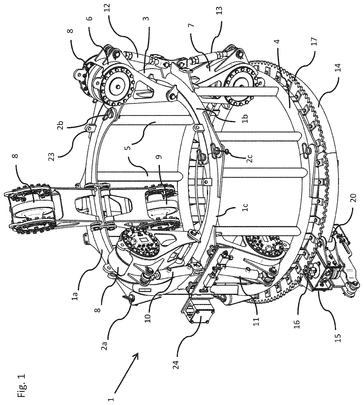
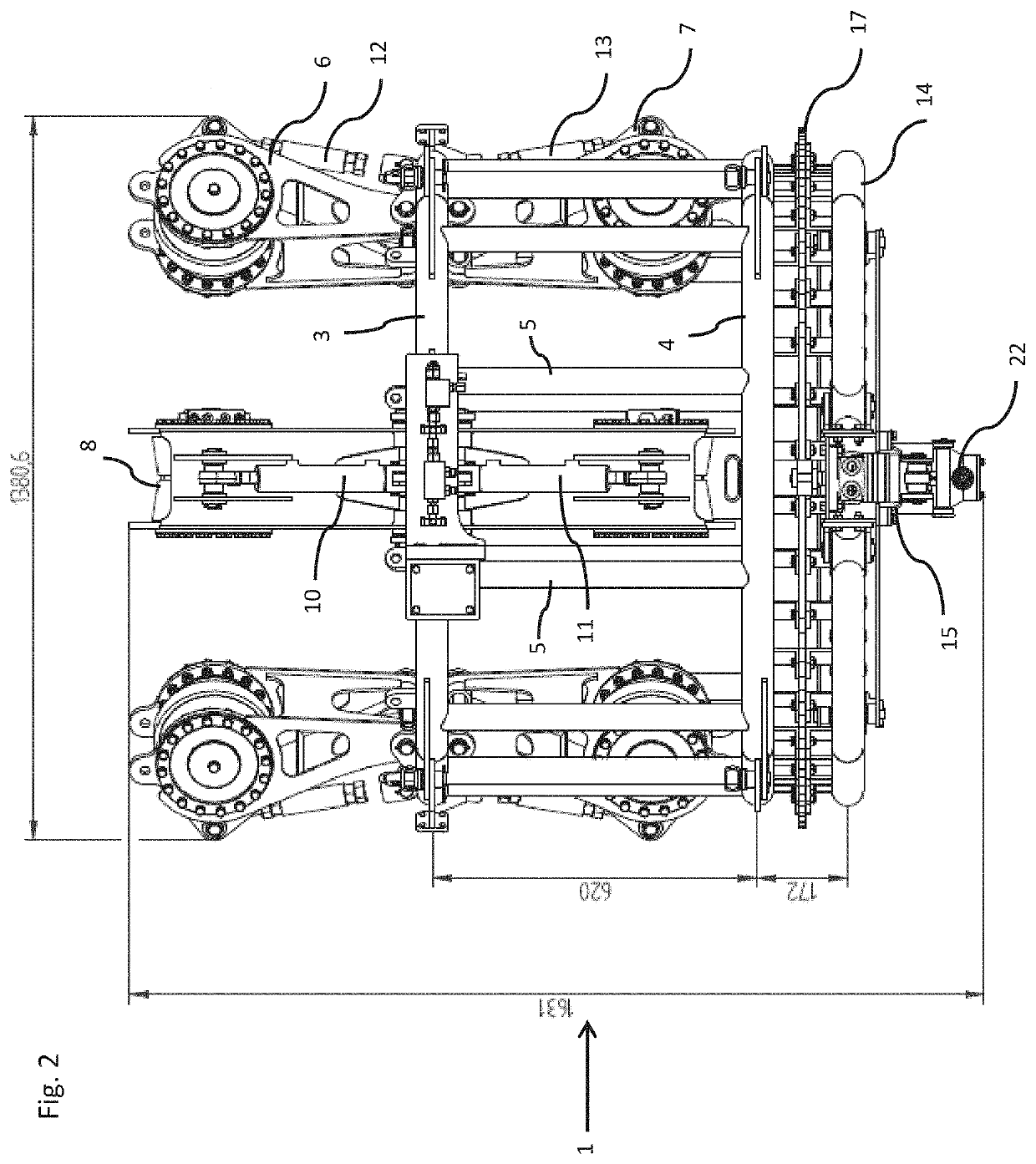
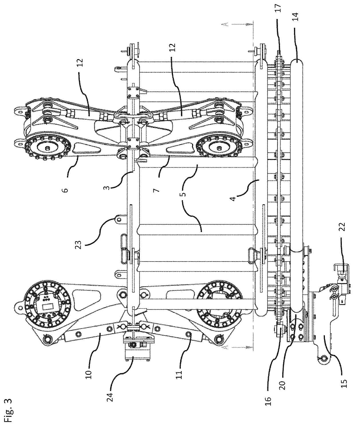
[0048]the invention is described below with reference to FIGS. 1 to 5. A cage or frame 1 comprises cage or frame segments or sections 1a, 1b, 1c which are removeably connected together at frame connection points 2a, 2b, 2c, for example using removable pins. In use, the frame segments 1a, 1b, 1c are assembled around the support structure 30 to be serviced. The frame segments 1a, 1b, 1c include lifting points 23 for attachment of cables or the like, for lifting the frame segments 1a, 1b, 1c into position and / or for retrieving them after use. Preferably, each frame segment 1a, 1b, 1c is light enough to be manually lifted into position.
[0049]The frame 1 comprises an upper support 3 and a lower support 4, interconnected by struts 5. In this embodiment, the upper and lower supports 3, 4 are circular in shape, and coaxial. The struts 5 extend generally vertically between the upper and lower supports 3, 4. The upper support 3, lower support 4 and struts 5 are preferably substantially rigid ...
second embodiment
[0070]In the second embodiment, the carriage 15 carries a camera 27, such as a video camera, in addition to a cleaning tool 22.
[0071]The apparatus may include one or more distance sensors, to determine the distance travelled along the support structure 30. The distance sensor(s) may for example determine the number of rotations of the wheel(s) 8, 9, for example by using one or more optical or magnetic angular position sensors.
[0072]The carriage 15 may include one or more rotational position sensors (e.g. optical or magnetic sensors) able to detect an absolute or relative circumferential position of the carriage 15 relative to the frame 1, for example by detecting reference position markings on the guide rail 14 or the gear track 17.
[0073]The distance sensor(s) and / or rotational position sensors (s) may be used to determine the position of the tool 22, carriage 15 or another part of the apparatus on the support structure 30. This may allow the apparatus to travel to a predetermined a...
fourth embodiment
[0108]The apparatus of the fourth embodiment is particularly suitable for servicing the towers of wind turbines. The positions of the upper and lower arms 6, 7 may be controlled independently to accommodate a tapered tower.
[0109]Alternative embodiments of the invention, which may be apparent to the skilled person on reading the above description, may fall within the scope of the invention as defined by the accompanying claims.
List of Parts and CorrespondingReference NumeralsPartReferenceCage or frame1Cage or frame segment1a, 1b, 1cFrame connection point2a, 2b, 2cUpper support3Lower support4Strut5Upper arm6Lower arm7Upper wheel / rotating8memberLower wheel / rotating9memberUpper hydraulic cylinder10Lower hydraulic cylinder11Upper adjustable length bar12Lower adjustable length bar13Guide rail14Carriage15Drive gear16Gear track17Carriage stop18Inner roller19Outer roller20Carriage arm21Tool22Lifting point23Hose clamp24Remote control unit25Controller26Camera27Power supply28Hydraulic hose29Str...
PUM
| Property | Measurement | Unit |
|---|---|---|
| diameter | aaaaa | aaaaa |
| diameter | aaaaa | aaaaa |
| diameter | aaaaa | aaaaa |
Abstract
Description
Claims
Application Information
 - R&D
- Intellectual Property
- Life Sciences
- Materials
- Tech Scout
- Unparalleled Data Quality
- Higher Quality Content
- 60% Fewer Hallucinations
Browse by: Latest US Patents, China's latest patents, Technical Efficacy Thesaurus, Application Domain, Technology Topic, Popular Technical Reports.
© 2025 PatSnap. All rights reserved.Legal|Privacy policy|Modern Slavery Act Transparency Statement|Sitemap|About US| Contact US: help@patsnap.com


