Power supply system for liquid crystal monitors

Inactive Publication Date: 2007-06-19
GLOBAL DISPLAY SOLUTIONS
View PDF11 Cites 11 Cited by
  • Summary
  • Abstract
  • Description
  • Claims
  • Application Information

AI Technical Summary

Benefits of technology

[0011]The aim thereof is to compensate the lamp equivalent negative impedance and to avoid the potential

Problems solved by technology

From the above it is clearly understandable that large monitors with high lighting power (such as those used with full atmospheric light) need an extremely large number of converters (such screens may need

Method used


Image

  • Power supply system for liquid crystal monitors
  • Power supply system for liquid crystal monitors
  • Power supply system for liquid crystal monitors

Examples


Embodiment Construction

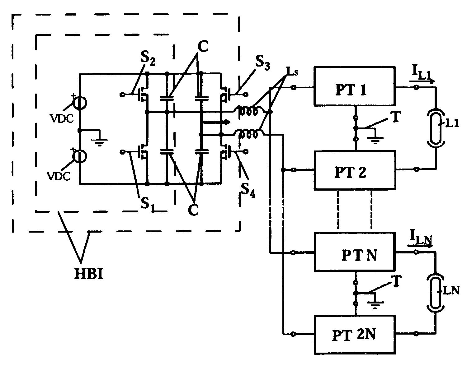
[0027]In some preferred, non restrictive embodiments of the invention it is possible to use a piloting apparatus for the PT1, PT2, PTN, PT2N piezoelectric transformers with series-connected inductors LS, since first a convenient measurement of the inductor LS provides ideal switching (soft-switching) and then, as the voltage wave form applied to the transformers PT1, PT2, PTN, PT2N is practically sinusoidal, it is possible to eliminate current peaks and the losses and troubles associated therewith, which would be caused by series-connecting the inductor LS.

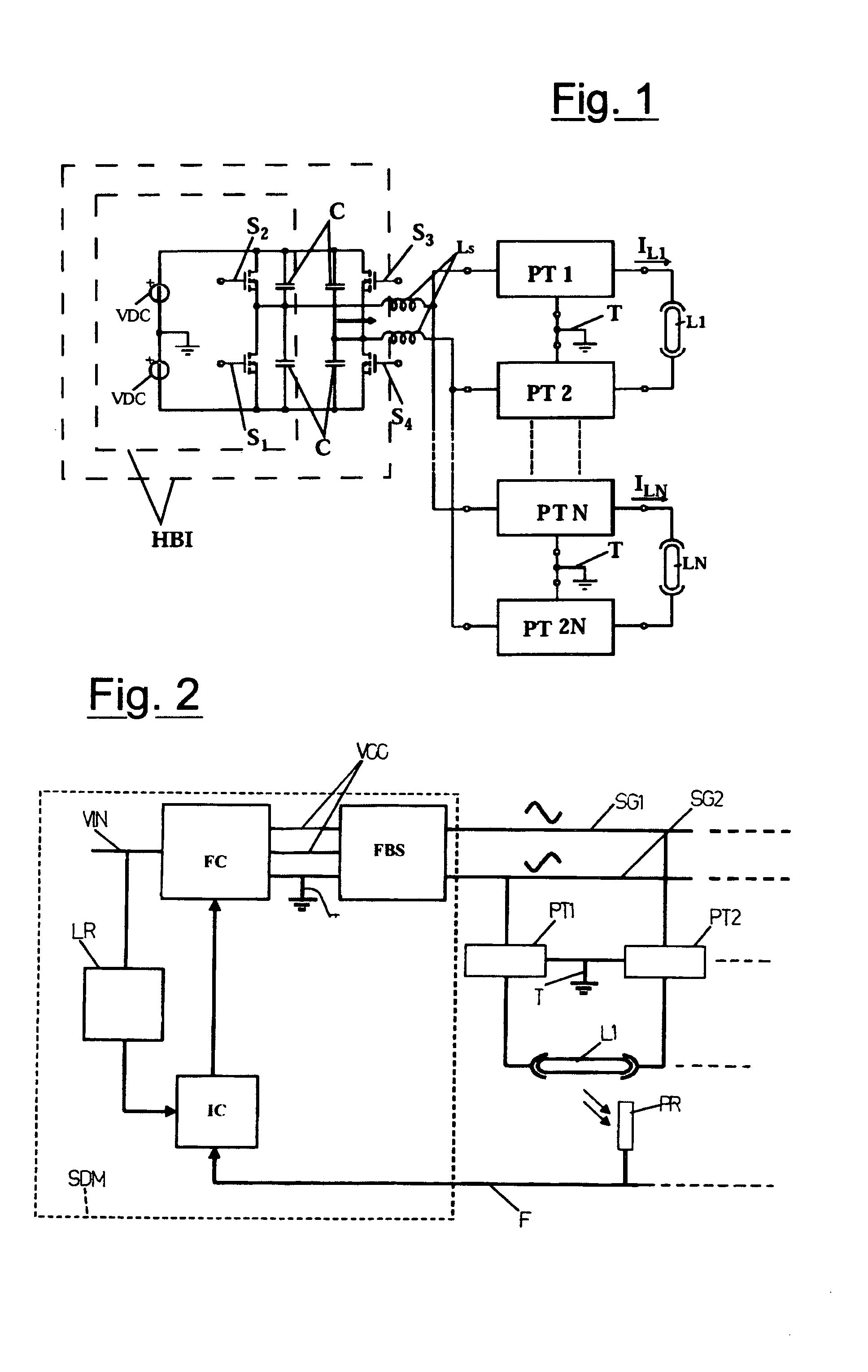
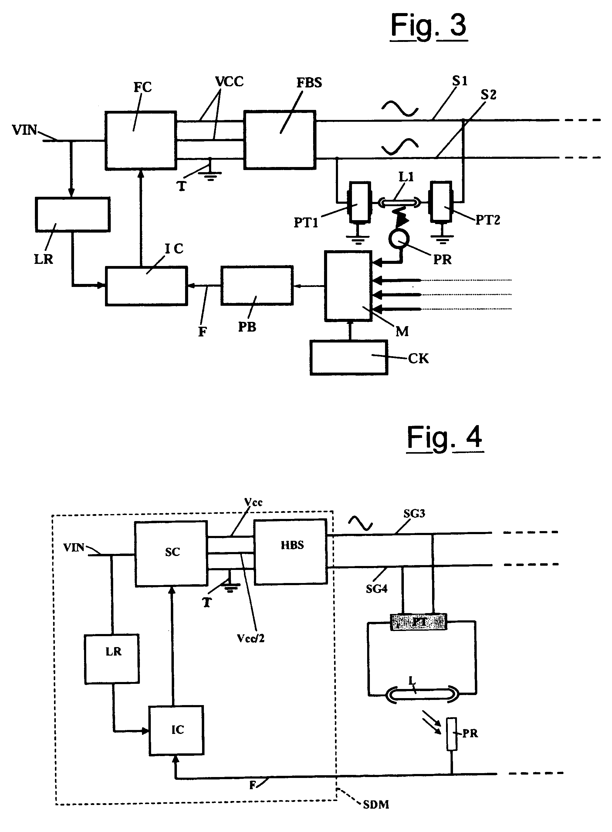
[0028]The illustrated piloting stage is based on the control of the MOSFET transistors S1, S2, S3, S4, which is provided by simultaneously piloting the pairs on the diagonals of the H-bridge (i.e., according to the sequence S1–S3, S2–S4) and by employing an integrated circuit and a pulse transformer with five windings.

[0029]The frequency of the generated square wave is fixed and it corresponds to the frequency which maximizes the ...


PUM


Abstract

A power supply system for liquid crystal monitors includes a first DC/AC converter (FBS, HBS) operating at predetermined frequency and duty-cycles and being fed by a second DC/DC converter (FC) which regulates the circuit voltage. The feeding system can feed all the fluorescent lamps (L, L1, LN) in the monitor through a bus connection which transmits the output sinusoidal voltage (SG1, SG2, SG3) from the first DC/AC converter (FBS, HBS) to the primary windings of a plurality of parallel connected piezoelectric transformers (PT, PT1, PT2, PTN, PT2N) which are connected with the fluorescent lamps (L, L1, LN).

Description

CROSS-REFERENCE TO RELATED APPLICATIONS[0001]Not ApplicableSTATEMENT REGARDING FEDERALLY SPONSORED RESEARCH OR DEVELOPMENT[0002]Not ApplicableINCORPORATION-BY-REFERENCE OF MATERIAL SUBMITTED ON A COMPACT DISK[0003]Not ApplicableREFERENCE TO A MICROFICHE APPENDIX[0004]Not ApplicableBACKGROUND OF THE INVENTION[0005](1) Field of the Invention[0006]The present invention refers to a power supply system for liquid crystal monitors.[0007]The more and more widespread use of liquid crystal (LCD) screens (monitors) in many applications, e.g. Personal Computers (PCs), measure instruments, bank counter terminals (Bancomat), information terminals in stations, airports, TVs, has rapidly caused the need to display alphanumeric characters and images extremely clearly with any kind of light (either natural or artificial) and, consequently, to generate adequate high intensity light.[0008](2) Description of Related Art[0009]At present, the use of cold cathode fluorescent lamps (CCFLs) and / or EEFL lamp...

Claims


Application Information

Patent Timeline
IPC IPC(8): H05B37/00H05B41/282H05B41/392
CPCH05B41/2822H05B41/3922
Inventor ONGARO, ANDREASPIAZZI, GIORGIOBUSO, SIMONETOMASIN, PAOLO
Owner GLOBAL DISPLAY SOLUTIONS
Why Eureka
Try Eureka