
Active position marker system for use in an MRI apparatus

a technology of active position and mri, applied in the direction of instruments, catheters, magnetic variable regulation, etc., can solve the problems of reducing the comfort and ease of use, limiting the flexibility of handling, and increasing the time needed to prepare an mr imaging procedure, etc., and achieves the effect of being easily and flexibly handled

Active Publication Date: 2015-02-05
KONINKLJIJKE PHILIPS NV
View PDF3 Cites 7 Cited by
  • Summary
  • Abstract
  • Description
  • Claims
  • Application Information

AI Technical Summary

Benefits of technology

The invention aims to solve the safety risks and difficulties in using active position markers. The technical effects of using a parametric amplifier for amplifying the received MR signal include low noise and simple circuit structure. Furthermore, the transmission of the MR signal in an upconverted microwave frequency band allows for the use of a small diameter cable and reduces RF common mode currents. These technical effects make the invention easier to handle, flexible, and safer.

Problems solved by technology

However, one major drawback of the above active markers and of interventional or non-interventional instruments comprising such an active marker is, that an RF cable connection is required for feeding the received MR signals from the active marker to a remote MR receiver or MR imaging apparatus.
On the one hand, such a cable reduces the comfort and ease of use and introduces mechanical safety risks, especially in case of an interventional instrument, limits the flexibility of handling, and increases the time needed to prepare an MR imaging procedure.
On the other hand, a (metallic) cable for connecting the active position marker with an MR receiver usually has to be guided inside and through an examination space of an MR imaging apparatus, so that it poses a potential safety risk due to resonant common mode currents which are induced on the cable by the RF excitation field emitted by the related RF transmit antenna of the MR imaging apparatus.

Method used


Image

  • Active position marker system for use in an MRI apparatus
  • Active position marker system for use in an MRI apparatus

Examples


Embodiment Construction

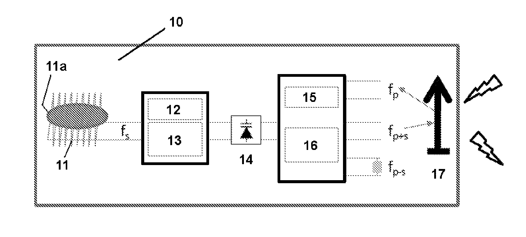
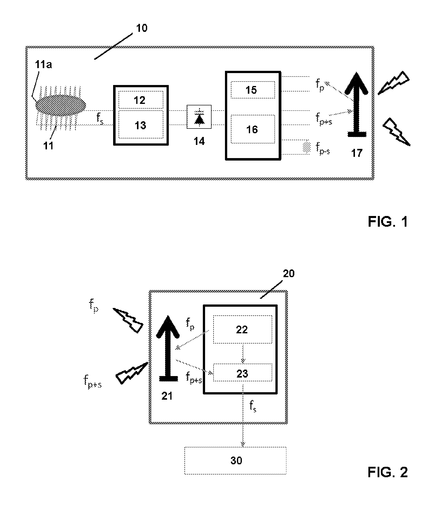
[0026]FIGS. 1 and 2 together show a schematic block diagram of the components of an active position marker system according to a first embodiment of the invention. Basically, the position marker system comprises at least one active position marker 10 according to FIG. 1 for receiving, amplifying, frequency-upconverting and transmitting local MR signals, and a remote transceiver unit 20 according to FIG. 2 for receiving and frequency-downconverting the transmitted local MR signals and for supplying these signals to an image processing unit 30 of an MR imaging apparatus.

[0027]According to the first embodiment, the transmission is conducted wirelessly and preferably in the microwave frequency range between about 1 and about 300 GHz, like e.g. in the 2.4 GHz band or another one of the ISM frequency bands like 24 GHz, 61 GHz, 122 GHz or 244 GHz etc. However, in principle also frequencies below the microwave frequency range, but substantially higher than the MR frequency might be used (e....


PUM


Abstract

An active position marker system comprising at least one active position marker (10) and a remote transceiver unit (20) for communicating with the position marker is disclosed. Basically, the position marker (10) comprises a local RF receive coil (11) for receiving MR signals which are excited in a local volume, and a parametric amplifier (14) for amplifying and upconverting the frequency of the received MR signal into at least one microwave sideband frequency signal. This microwave signal is transmitted wirelessly or wire-bound to the transceiver unit for downconverting the same and supplying it to an image processing unit of an MR imaging apparatus.

Description

FIELD OF THE INVENTION[0001]The invention relates to an active position marker system comprising at least one active position marker and a remote transceiver unit for communicating with the at least one position marker, for use in an MR imaging apparatus. A position marker is considered “active” in the sense, that it is provided for receiving MR signals substantially only from a local volume after RF excitation of the local volume which volume at least substantially surrounds or which is at least substantially surrounded by the marker or adjacent to the marker, so that on the basis of these “local” MR signals the position of the marker can be determined and / or imaged by means of an MR imaging apparatus especially in an MR image of an examination object with a desired accuracy.[0002]Further, the invention relates to a medical device in the form of an interventional or non-interventional instrument like a catheter, a surgical device, a biopsy needle, a pointer or another invasive or n...

Claims


Application Information

Patent Timeline
Patent Type & Authority Applications(United States)
IPC IPC(8): G01R33/28A61B19/00A61M25/01G01R33/36
CPCG01R33/287G01R33/36A61B2019/5454A61M25/0127A61B19/54G01R33/3621G01R33/3692A61B90/39A61B2090/3954
Inventor LIPS, OLIVERKRUEGER, SASCHAVAN HELVOORT, MARINUS JOHANNES ADRIANUS MARIA
Owner KONINKLJIJKE PHILIPS NV
Learn More