Near-infrared laser spot field-of-view parameter measurement device and method

A laser parameter and laser spot technology, which is applied in the direction of measuring devices, optical devices, instruments, etc., can solve the problems of large measurement errors, no automatic test of infrared laser spots, and difficulty in defining the edge of laser spots.

Active Publication Date: 2014-04-30
XIAN TECHNOLOGICAL UNIV
View PDF5 Cites 14 Cited by
  • Summary
  • Abstract
  • Description
  • Claims
  • Application Information

AI Technical Summary

Problems solved by technology

In the prior art, there is an infrared laser spot measurement board, which mainly uses the panel as the substrate, and obtains the laser spot size by uniformly printing a layer of infrared quenching material on the surface of the panel in conjunction with lighting; in addition, there are laser-based The infrared spot measurement method of the shooting machine, etc., these measurement methods cannot realize automatic measurement, and because the edge of the laser spot is difficult to

Method used


Image

  • Near-infrared laser spot field-of-view parameter measurement device and method
  • Near-infrared laser spot field-of-view parameter measurement device and method
  • Near-infrared laser spot field-of-view parameter measurement device and method

Examples


Embodiment 1

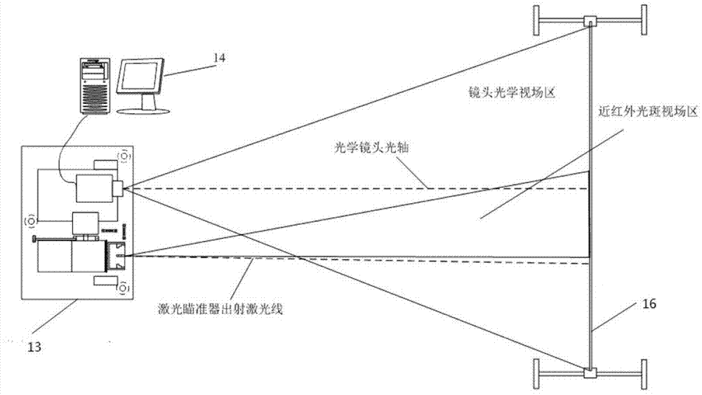
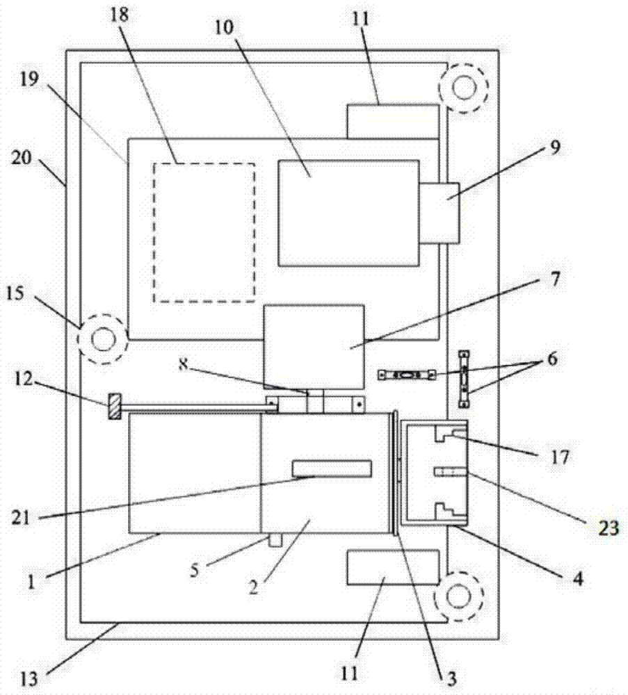
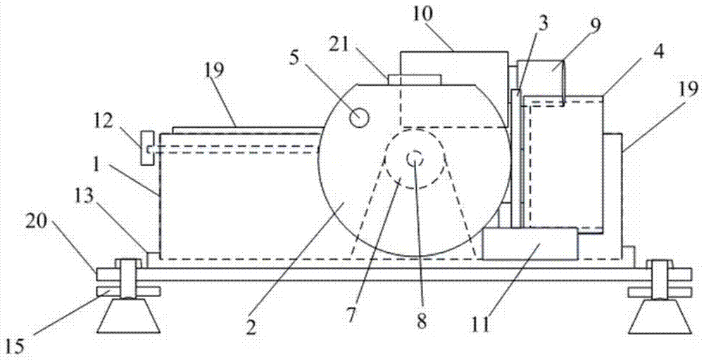
[0040] Such as Figure 1-4 As shown, a near-infrared laser spot field parameter measurement device is shown, which includes a near-infrared laser parameter test bench 13, a computer 14 and a calibration grid plate 16, wherein processing and calculation software are installed on the computer 14, and the near-infrared laser The parameter test bench 13 includes an emitting device capable of emitting near-infrared laser light. The measuring device also includes a chassis base 20 on which the near-infrared laser parameter test bench 13 can be fixed, and the chassis base 20 is placed horizontally by at least three horizontal adjustment bases 15 installed at its edge On the ground or on the platform, each level adjustment base 15 can be used to adjust the height of the chassis base 20 to ensure that the whole near-infrared laser parameter test bench 13 is in a horizontal state, and the chassis base 20 is also provided with two levels Observing the water bubbles is used to observe th...

Embodiment 2

[0063] According to the operation steps of Example 1, if the adjustment of the pitch direction rotation adjustment mechanism 2 and the concentric shaft rotation adjustment mechanism 4 in the specific step 5 are measured, the spot of the calibration laser 23 is located on the calibration grid plate 16, and the rotation adjustment of the pitch direction is recorded. The visible laser sight 21 above the mechanism 2 is marking the new coordinate point of the grid plate See Figure 5 , then ∠OFO 2 That is, the angle β between the centerline of the near-infrared laser exit spot and the main axis of the laser product. According to the coordinates O(x,y), o 0 (x 0 ,y 0 ) to obtain OO 2 and OO 0 Distance, by ΔOFO 2 , ΔO 2 o 0 F and ΔOO 0 F, combined with the pitch angle θ read by the 13-bit angle encoder 7, β can be calculated.

[0064] β = arccos OF 2 + ...


PUM


Abstract

The invention relates to a near-infrared laser spot field-of-view parameter measurement device. The near-infrared laser spot field-of-view parameter measurement device comprises a near-infrared laser parameter test bench, a computer and a calibration grid plate, wherein the near-infrared laser parameter test bench comprises an emitting device capable of emitting near-infrared laser, the calibration grid plate is arranged at the position having a certain distance from the near-infrared laser parameter test bench, and the calibration grid plate is orthogonal to the laser emitted by the near-infrared laser parameter test bench. According to the near-infrared laser spot field-of-view parameter measurement device and method, border dotted lines of near-infrared laser spots are effectively found by rotating a holder to adjust the laser emitting direction and adopting image processing techniques, the sizes of the fields of view of various near-infrared laser spots can be measured effectively, the near-infrared laser spot field-of-view parameter measurement device has incomparable advantages which cannot be achieved by other equipment, is flexible in operation and simple, and visual processing results can be provided.

Description

technical field [0001] The invention belongs to the technical field of laser testing, and in particular relates to a near-infrared laser spot parameter measuring device and a measuring method. Background technique [0002] In the field of navigation and laser detection, the size of the laser spot restricts the performance of laser series weapons and ammunition. Under the same power condition, if the laser spot is too large, that is, the field of view is too large, which means that the detection performance of this type of ammunition is reduced at the same distance. , if the laser spot is too small, that is, the field of view is too small, the laser energy will converge, which will help improve the detection performance of ammunition, and the detection distance will increase, but if the laser field of view is too small, the detection surface will also become smaller, and there will be detection blind spots, reducing The capture rate of the detection is improved, especially th...

Claims


Application Information

Patent Timeline
IPC IPC(8): G01B11/00G01B11/26G01B11/28
Inventor 雷志勇李翰山高俊钗王泽民雷鸣李静闫克丁
Owner XIAN TECHNOLOGICAL UNIV
Why Eureka
Try Eureka