Method for actively controlling electric potential at the head/disk interface of a magnetic recording disk drive

a magnetic recording disk and electric potential technology, applied in the direction of recording information storage, maintaining head carrier alignment, instruments, etc., can solve the problems of drive failure, read/write errors, drive failure, etc., and achieve the effect of eliminating an electrical potential differen

Active Publication Date: 2007-06-19
WESTERN DIGITAL TECH INC
View PDF11 Cites 37 Cited by
  • Summary
  • Abstract
  • Description
  • Claims
  • Application Information

AI Technical Summary

Benefits of technology

[0013]The present invention provides a technique for determining the optimum bias voltage that should be applied between a slider body and a disk for eliminating an electrical potential difference that exists between the slider body and the disk, such as a contact potential.
[0014]The advantages of the present invention are provided by a system and a method for eliminating an electrical potential difference between a slider body and a hard disk of a hard disk drive. According to the present invention, a flying-height spacing of the slider body between the slider body and the hard disk is detected. A predetermined bias voltage is applied between the slider body and the hard disk that includes a DC component and an AC component and that is based on the detected flying-height spacing of the slider body. One aspect of the present invention provides that the flying height spacing of the slider body is detected based on determining a minimum slider-to-disk clearance change from a design flying height of the slider at a frequency of the AC component as the DC component of the predetermined bias voltage is varied. Another aspect of the present invention provides that the flying height spacing of the slider body is detected based on detecting a minimum electrodynamic response of the slider to a first harmonic of the AC frequency of the AC component as the DC component is varied. Still another aspect of the present invention provides that the flying-height of the slider body is detected based on a minimum interference between the slider body and the hard disk at a frequency of the AC component as the DC component is varied.
[0015]One embodiment of the present invention detects the flying-height spacing of the slider body using a Laser Doppler Vibrometer. Another embodiment of the present invention detects the flying-height spacing of the slider body based on a magnitude of magnetic readback signal that is sensed by a read element on the slider body at the frequency of the AC component as a magnitude of the DC component is varied. For these embodiments of the present invention, the AC component can be a swept-frequency AC signal or a single-frequency AC signal. Yet another embodiment of the present invention detects the flying-height of the slider body based on a minimum variation of current that flows on and off the slider body as the DC component of the bias voltage is varied. Still another embodiment of the present invention detects the flying-height spacing of the slider body is based on a minimum resistance of a magnetoresistive element as the DC component is varied. A further embodiment of the present invention detects the flying-height spacing of the slider body based on an output of a piezoelectric sensor or an acoustic emission sensor sensing contact between the slider body and the hard disk as the DC component is varied.

Problems solved by technology

The polarity of the lubricant in the presence of an electrostatic field at the head-disk interface can cause lubricant to be removed from the disk surface and possibly be depleted from the disk surface.
The removed lubricant is usually picked up by the slider and can lead to drive failure.
Once concentrated, the lubricant can form droplets that can lead to read / write errors when the droplets of lubricant enter the head-disk interface.
Yet another potential problem that is caused by the electrostatic force is an increased vibrational coupling between slider body 201 and disk 202, leading to larger modulations of the slider-disk spacing.

Method used


Image

  • Method for actively controlling electric potential at the head/disk interface of a magnetic recording disk drive
  • Method for actively controlling electric potential at the head/disk interface of a magnetic recording disk drive
  • Method for actively controlling electric potential at the head/disk interface of a magnetic recording disk drive

Examples


Embodiment Construction

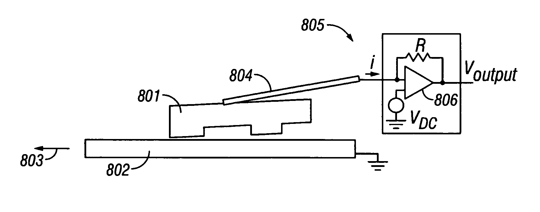
[0032]The present invention provides a technique for determining the optimum bias voltage that should be applied between a slider body and a disk for eliminating an electrical potential difference that exists between the slider body and the disk, such as a contact potential caused by tribocharging or by the material differences of slider and disk. By eliminating the electric field between the slider body and the disk, the slider flying height is increased to the maximum design flying height of the slider. Removal and depletion of lubricant from the disk surface caused by electrostatic forces are also eliminated. Accordingly, because lubricant is not removed from the disk, lubricant does not become concentrated in areas on the slider body and lubricant droplets do not form. Consequently, read / write errors caused by lubricant droplets in the head-disk interface are avoided. Further, vibrational coupling between the slider body and the disk is reduced because the electrostatic force be...


PUM

PropertyMeasurementUnit
heightaaaaaaaaaa
dynamic pitch angleaaaaaaaaaa

Abstract

An electrical potential difference between a slider body and a hard disk of a hard disk drive is eliminated based on the flying-height spacing of the slider body between the slider body and the hard disk. A predetermined bias voltage is applied between the slider body and the hard disk that includes a DC component and an AC component and that is based on the detected flying-height spacing of the slider body. The flying-height spacing can be detected based a minimum slider-to-disk clearance change from a design flying height of the slider at a frequency of the AC component as the DC component of the predetermined bias voltage is varied. Alternatively, the flying-height spacing can be detected based on a minimum electrodynamic response of the slider to a first harmonic of the AC frequency of the AC component as the DC component is varied.

Description

CROSS-REFERENCED TO RELATED APPLICATION[0001]The present application is related to co-pending and co-assigned patent application Ser. No. 10 / 691,752, entitled “Magnetic Recording Disk Drive With Actively Controlled Electric Potential At The Head / Disk Interface,” which is filed concurrently herewith and is incorporated by reference herein.BACKGROUND OF THE INVENTION[0002]1. Field of the Invention[0003]The present invention relates to hard disk drives (HDDs). More particularly, the present invention relates to a technique for detecting and eliminating an electrical potential difference between a slider body and a disk surface of an HDD, such as a contact potential caused by material differences between the slider and the disk or a potential generated by tribocharging.[0004]2. Description of the Related Art[0005]FIG. 1 shows an exemplary hard disk drive (HDD) 100 having a dual-stage servo system for positioning a slider assembly 101 over a selected concentric data information track on ...

Claims


Application Information

Patent Timeline
Patent Type & Authority Patents(United States)
IPC IPC(8): G11B5/02G11B5/03G11B5/60G11B21/02
CPCG11B5/6005
Inventor BAUMGART, PETER MICHAELKNIGGE, BERNHARDMATE, MATHEW
Owner WESTERN DIGITAL TECH INC
Why Eureka
Try Eureka