Maximum likelihood decoding

a probability decoding and probability technology, applied in the field of probability decoding, can solve the problems of increasing the number of transmitted data streams, noise, and adding to the signal received from the transmitting antenna

Active Publication Date: 2007-06-19
APPLE INC
View PDF6 Cites 87 Cited by
  • Summary
  • Abstract
  • Description
  • Claims
  • Application Information

AI Technical Summary

Benefits of technology

[0008]The present invention relates generally to maximum likelihood decoding for detecting signals transmitted over a Multiple-Input-Multiple-Output (MIMO) channel in which the number of possible transmit signal points considered in the method is limited to those located in an orthotope centred on a noise corrupted transmit signal point derived from the received signal, which orthotope has sides parallel to the axes of the multi-dimensional input space. With the orthotope having sides parallel to the axes, the problem of determining whether a given transmit signal point is in the orthotope comprises a simple comparison of the locations of the sides of the orthotope with the corresponding elements of the vectors defining the possible transmit points.
[0021]The first, second and third aspects of the present invention reduce the complexity of the problem of determining whether a given transmit signal point is to be considered as a candidate transmit signal point or not. This is achieved by selecting candidate transmit signal points located within an orthotope with at least some of its sides parallel to the corresponding axes of the input space. Then to determine whether a given transmit signal point is within the orthotope, a simple comparison can be carried out of the elements of the vectors defining the possible transmit signal point with the location of a corresponding parallel side of the orthotope. This is a less complex way of reducing the number of candidate transmit points in relation to which more complicated processing has to be carried out than is known in the prior art.
[0052]The fourth, fifth and sixth aspects of the present invention comprise the method of Parallelotope decoding. The main advantage of Parallelotope decoding over Generalised Sphere Decoding is that locating the input space lattice points which fall inside the orthotope aligned with the coordinates axes is simple, requiring no calculation, only comparisons. Locating input space lattice points which fall inside a hyperellipsoid as for GSD is computationally expensive.
[0084]The seventh to ninth aspects of the present invention relate to orthotope sphere decoding, which is a hybrid of generalised sphere decoding and parallelotope decoding. It has the advantage of being computationally less complex than either generalised sphere decoding or parallelotope decoding for most MIMO channels.

Problems solved by technology

In addition, at the receive antennas, noise will be present, which adds to the signal received from the transmit antennas.
A problem with MLD is when the number N of transmit antennas, ie. the number of transmitted data streams increases.
This problem is further exacerbated when a more complex modulation scheme such as 4-QAM or 16QAM is used to send more data bits across the channel simultaneously.
For many situations of practical interest the number of possible ideal signals is simply too high and the computational load becomes unmanageable.
The problem with the GSD is that the search to identify transmitted signal points in the input signal space lying within the hyperellipsoid can have a high computational load.

Method used


Image

  • Maximum likelihood decoding
  • Maximum likelihood decoding
  • Maximum likelihood decoding

Examples


Embodiment Construction

[0108]There will now be described by way of example the best mode contemplated by the inventor for carrying out the invention. In the following description, numerous specific details are set out in order to provide a complete understanding of the present invention. It will be apparent, however, to those skilled in the art that the present invention may be put into practice with variations of the specific.

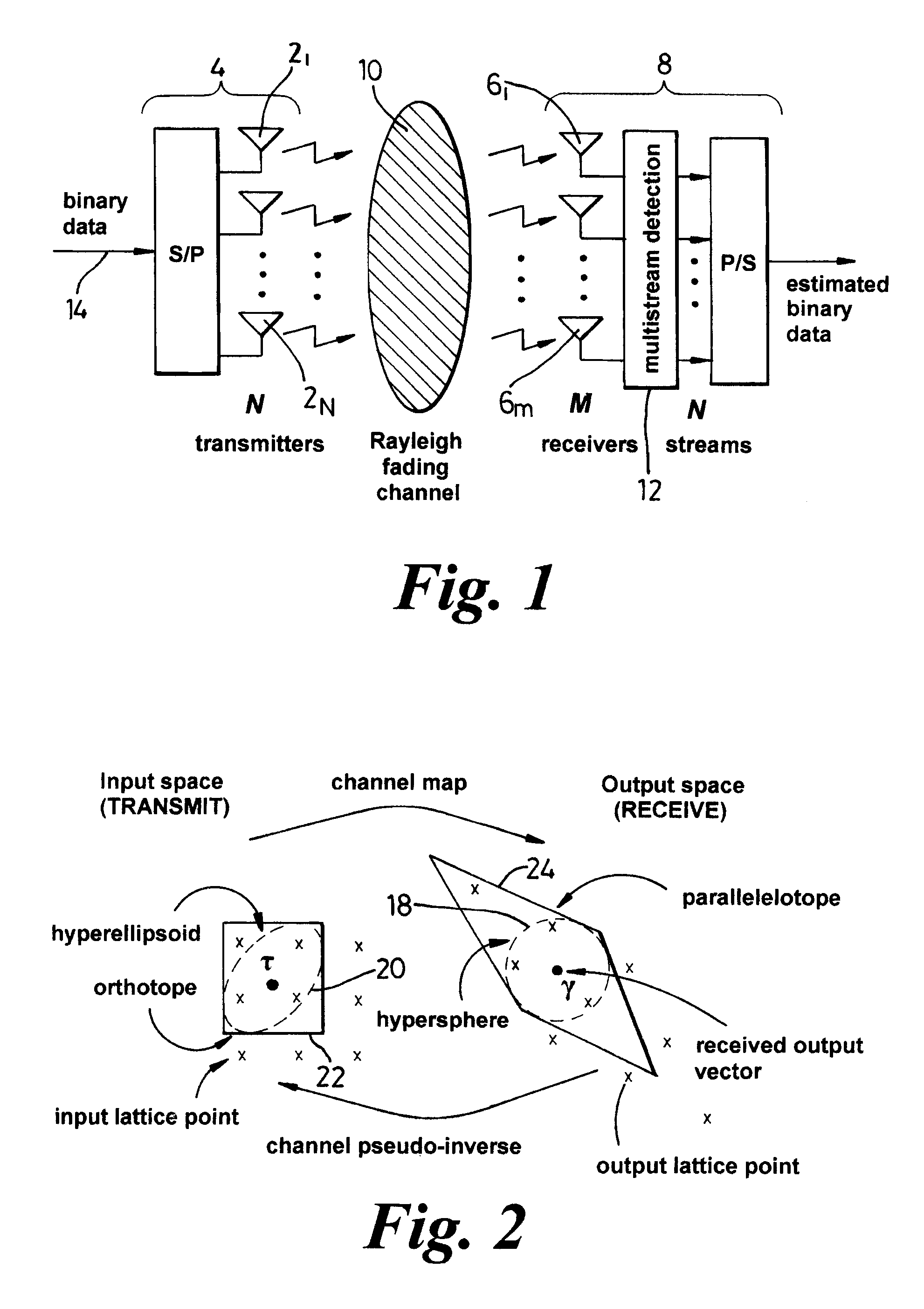
[0109]With reference to FIG. 1, the present invention relates to the detection of information symbols, or data, sent using N multiple co-channel transmit antennas (21 . . . 2N) of a transmitter (4) of a single entity and received by using M multiple co-channel receive antennas (61 . . . . 6M) of a receiver (8) of a single entity over a Multiple-Input-Multiple-Output (MIMO) channel (10) of a wireless communications system. The single entities (4, 8) may, for example, be a mobile user equipment or a base station of the wireless communications system. The MIMO channel may be between tw...


PUM


Abstract

A method of maximum likelihood decoding for detecting the signals transmitted over a Multiple-Input-Multiple-Output (MIMO) channel of a communication system in which there are N co-channel transmit antennas and M co-channel receive antennas. In a first method an orthotope (22) is generated in input signal space centred on an approximate transmit signal point τ which is an inverse mapping from an actual received signal point (y) in output signal space. Only possible transmit points located within the orthotope are considered as candidate points and are transformed into corresponding candidate receive signal points in output signal space. The Euclidean distance between the candidate receive signal points and the actual signal point is calculated and the closest candidate receive signal is selected as the detected received point. In an alternative method, the orthotope is constructed as the smallest such orthotope which can contain a hyperellipsoid (20) in input signal space, which hyperellipsoid is a transformation from output signal space of a hypersphere (18) centred on the actual received signal point (y). Those transmit signal points which lie within the orthotope (22) but outside of the ellipsoid (20) are discarded and the remaining points within the orthotope are considered as candidate points, in the same way as described above.

Description

FIELD OF THE INVENTION[0001]This invention relates to a method and apparatus for carrying out Maximum Likelihood Decoding (MLD) of multi-stream data transmissions over a Multiple-Input-Multiple-Output (MIMO) channel of a communications system.BACKGROUND OF THE INVENTION[0002]In a typical MIMO channel of a wireless communications system, as depicted in FIG. 1, the number of co-channel transmit antennas is denoted by N and the number of co-channel receive antennas is denoted by M. Each transmit antenna sends a signal that represents digital information and each receive antenna receives a signal from each transmit antenna. Generally, the transmitted signal will be changed by propagation between the transmit and receive antennas, ie. by propagation across the channel. For example, the transmitted signal may be subject to ‘flat fading’, in which the effect of propagation across the channel can be represented by multiplication of the transmitted signal by a number, which number represents...

Claims


Application Information

Patent Timeline
Patent Type & Authority Patents(United States)
IPC IPC(8): H03D1/04
CPCH04L1/0054H04L25/03242H04L2025/03426
Inventor HASSELL SWEATMAN, CATHERINETHORNPSON, JOHN SCOTT
Owner APPLE INC
Why Eureka
Try Eureka