Optical communication system, method for supplying pump light, and distributed Raman amplifying apparatus

Inactive Publication Date: 2007-06-19
FUJITSU LTD
View PDF17 Cites 13 Cited by
  • Summary
  • Abstract
  • Description
  • Claims
  • Application Information

AI Technical Summary

Benefits of technology

[0030]In the pump light supplying method, it is possible to monitor occurrence of optical damage at a supplying destinat

Problems solved by technology

Meanwhile, when the optical power is reduced,

Method used


Image

  • Optical communication system, method for supplying pump light, and distributed Raman amplifying apparatus
  • Optical communication system, method for supplying pump light, and distributed Raman amplifying apparatus
  • Optical communication system, method for supplying pump light, and distributed Raman amplifying apparatus

Examples


first embodiment

Structure of a First Embodiment

[0057]The first embodiment relates to an optical communication system according to the present invention.

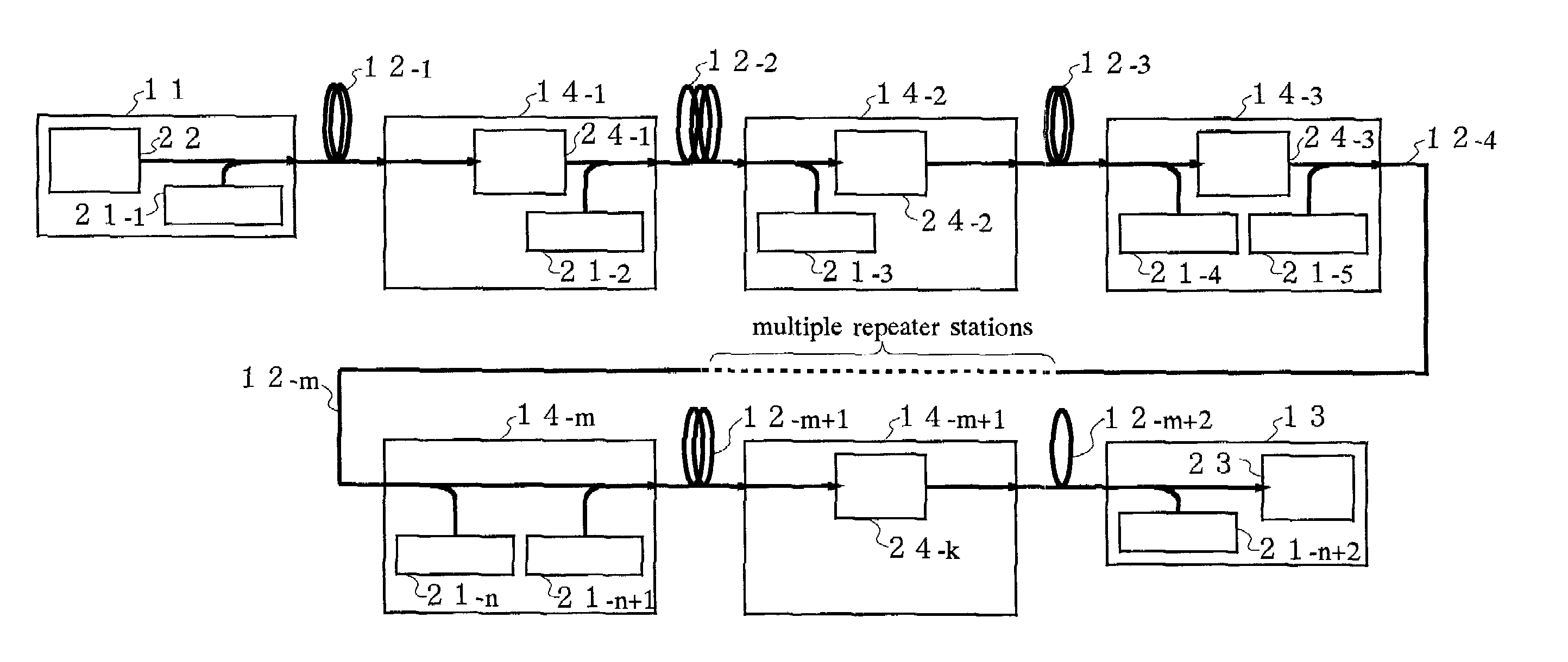
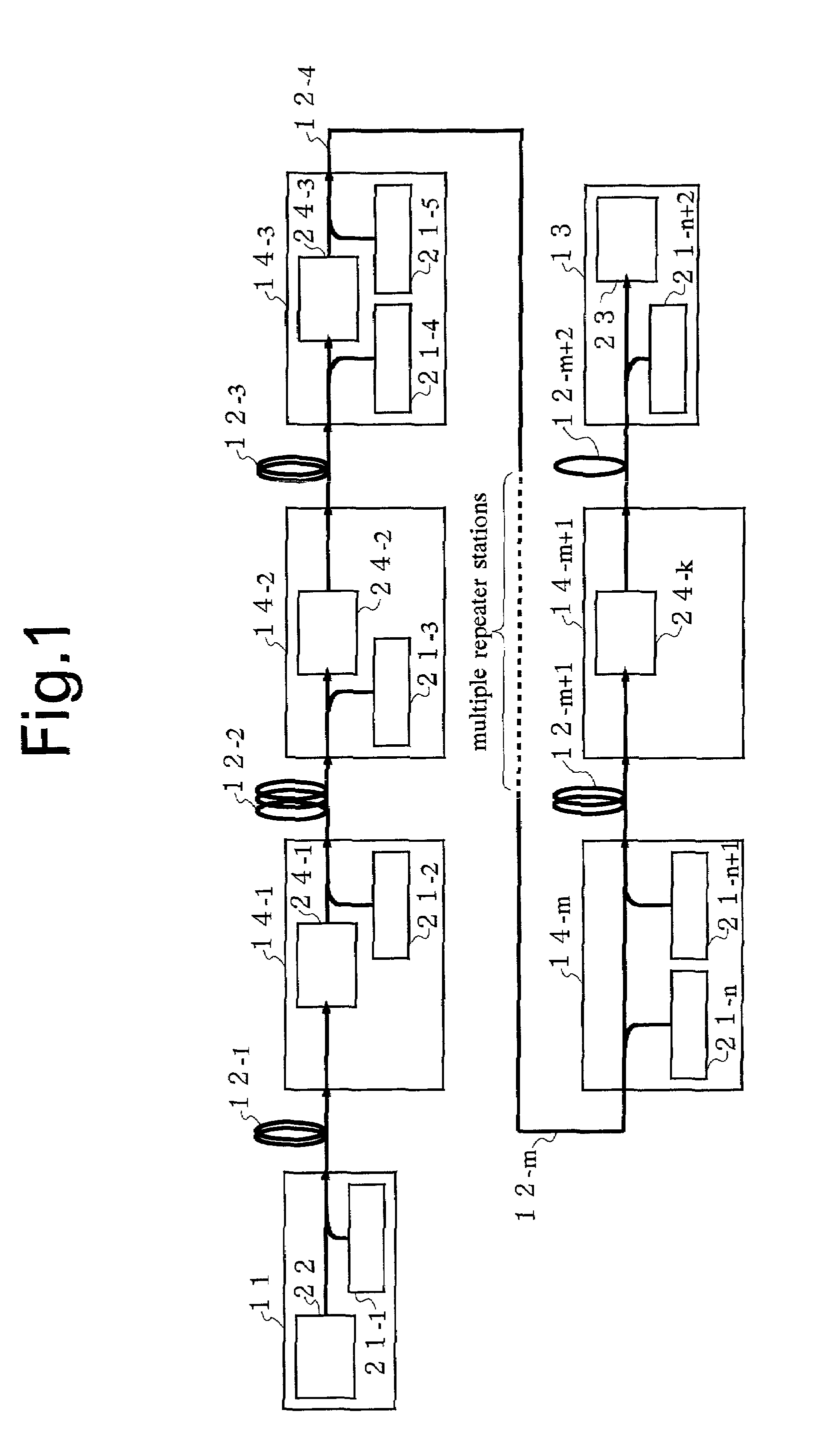
[0058]FIG. 1 shows the structure of the optical communication system according to the first embodiment.

[0059]In FIG. 1, the optical communication system is structured by including a transmitting station 11, a optical transmission line 12 which transmits an optical signal sent out from the transmitting station 11, a receiving station 13 which receives the optical signal outputted from the optical transmission line 12, and a repeater station 14 which is provided at one point or more in the optical transmission line 12. Pump light sources 21 which supply pump light to the optical transmission line 12 are provided in at least two of the transmitting station 11, the receiving station 13 and the repeater stations 14. In the first embodiment, a pump light source 21-1 is provided in the transmitting station 11, a pump light source 21-2 is provided in a repe...

second embodiment

Structure of a Second Embodiment

[0106]The second embodiment relates to an optical communication system according to the present invention.

[0107]FIG. 5 shows the structure of the optical communication system according to the second embodiment.

[0108]In FIG. 5, the optical communication system is structured by including a transmitting station 51, an optical transmission line 52 which transmit optical signals with a plurality of wavelengths sent out from the transmitting station 51, a receiving station 53 which receives the optical signals outputted from the optical transmission line 52, and a repeater station 54 which is provided at one point or more in the optical transmission line 52.

[0109]Further, a backward pumping part 63 is provided at least one of the transmitting station 51, the receiving station 53 and the repeater stations 54. In the second embodiment, the backward pumping parts 63 are provided in repeater stations 54-1, 54-2 and the receiving station 53, and the backward pum...

third embodiment

Structure of a Third Embodiment

[0162]The third embodiment relates to an optical communication system according to the present invention.

[0163]FIG. 10 shows the structure of the optical communication system according to the third embodiment.

[0164]In FIG. 10, the optical communication system includes a transmitting station 101 in which a WDM optical signal is generated, an optical transmission line 102 which transmits the generated WDM optical signal, and a receiving station 103 which receives and processes the transmitted WDM optical signal, and further, one or more repeater station 104 is provided at some midpoint in the optical transmission line 102, as necessary.

[0165]The repeater station 104 has, as will be later-described, a function of supplying pump light used for Raman amplification in the optical transmission line 102, a function of amplifying the optical signal inside its own station, an ADM (add / drop multiplexer) function for branching / inserting / passing the optical signal ...


PUM


Abstract

An optical communication system according to the invention comprises: a transmitting station 11; an optical transmission line 12 for transmitting an optical signal sent from the transmitting station 11; a receiving station 13 for receiving the optical signal outputted from the optical transmission line 12; a repeater station 14 provided at one point or more in the optical transmission line 12; and pump light sources 21 provided in at least two of the stations 11, 13, 14, for supplying pump light to the optical transmission line 12, wherein the pump light has two types or more of wavelength. It is possible to obtain a substantially flat gain as a function of wavelength in the whole optical communication system since the pump lights with different wavelengths are supplied from a plurality of points in the optical transmission line 12 and an optical signal is amplified with various Raman gain coefficients.

Description

CROSS REFERENCE TO RELATED APPLICATION[0001]This application is a continuation application of International Application PCT / JP00 / 05750, Filed Aug. 25, 2000, and designating the U.S.BACKGROUND OF THE INVENTION[0002]1. Field of the Invention[0003]This invention relates to an optical communication system, a pump light supplying method and a distributed Raman amplifying apparatus which supply pump light in such a manner to secure flatness of gain as a function of wavelength, safety of an operator and avoidance of optical damage, in the optical communication system where Raman amplification is performed in an optical transmission line.[0004]2. Description of the Related Art[0005]Recently, with the objective of constructing a future multimedia network, optical communication apparatus with ultra-long distance and large capacity is required. Research and development on wavelength-division multiplexing (hereinafter abbreviated to “WDM”) is carried on in order to realize the large capacity, b...

Claims


Application Information

Patent Timeline
IPC IPC(8): H04J14/02H04B10/291H04B10/293
CPCH04B10/2916H04B10/2935
Inventor HOSHIDA, TAKESHITERAHARA, TAKAFUMI
Owner FUJITSU LTD
Why Eureka
Try Eureka