
Task concurrency management design method

Inactive Publication Date: 2007-06-19
INTERUNIVERSITAIR MICRO ELECTRONICS CENT (IMEC VZW) +2
View PDF10 Cites 37 Cited by
  • Summary
  • Abstract
  • Description
  • Claims
  • Application Information

AI Technical Summary

Benefits of technology

[0016]The method described above, wherein said essentially digital system being modelled as a set of or a plurality of processors and said generating of a plurality of static schedulings comprising solving of a first time-constraint cost optimization problem wherein thread nodes are assigned to said processors and said cost essentially being related to said processors. The method described above, wherein said generating of a plurality of static scheduling generates cost-cycle budget trade-off curves for at least two thread frames, said cost-cycle budget trade-off curves comprise of points representing said static schedulings. The method described above, wherein said dynamic scheduling comprises of a second time-constraint cost optimization problem. The method described above, wherein said first time-constraint cost optimization optimizes a cost function comprising at least energy consumption of a processor executing a scheduled thread node. The method described above, wherein said second time-constraint cost optimization optimizes a cost function comprising at last energy consumption of a processor Executing a scheduled thread node. The method described above, wherein said generating of static schedulings for a thread frame being capable of modifying the amount of thread nodes within said thread frame. The method describing above, wherein said tasks are communicating. The method described above, wherein non-deterministic behavior of said essentially digital system is described by the dynamical scheduling of the thread frames while the deterministic behavior is modelled inside the thread frames by the static scheduling of the thread nodes. The method described above wherein said designing step comprises the step of partitioning said at least partially scheduled description over a plurality of processors. The method describe above, wherein said designing step comprises the step of performing a hardware / software partitioning step on said at least partially scheduled description. The method described above, wherein before generating said plurality of static schedulings for at least one thread frame a task concurrency improving transformation on said thread frame is performed.
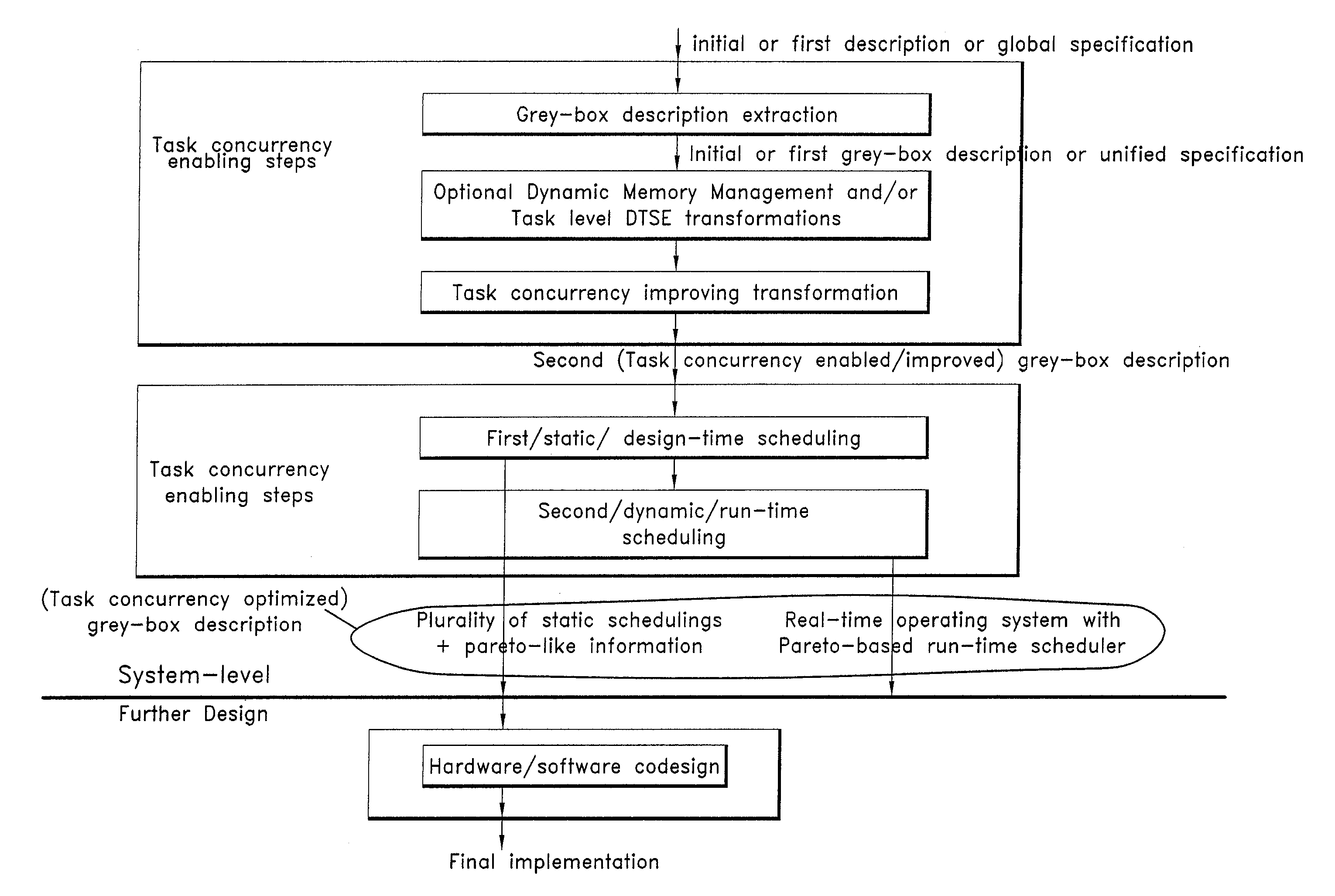
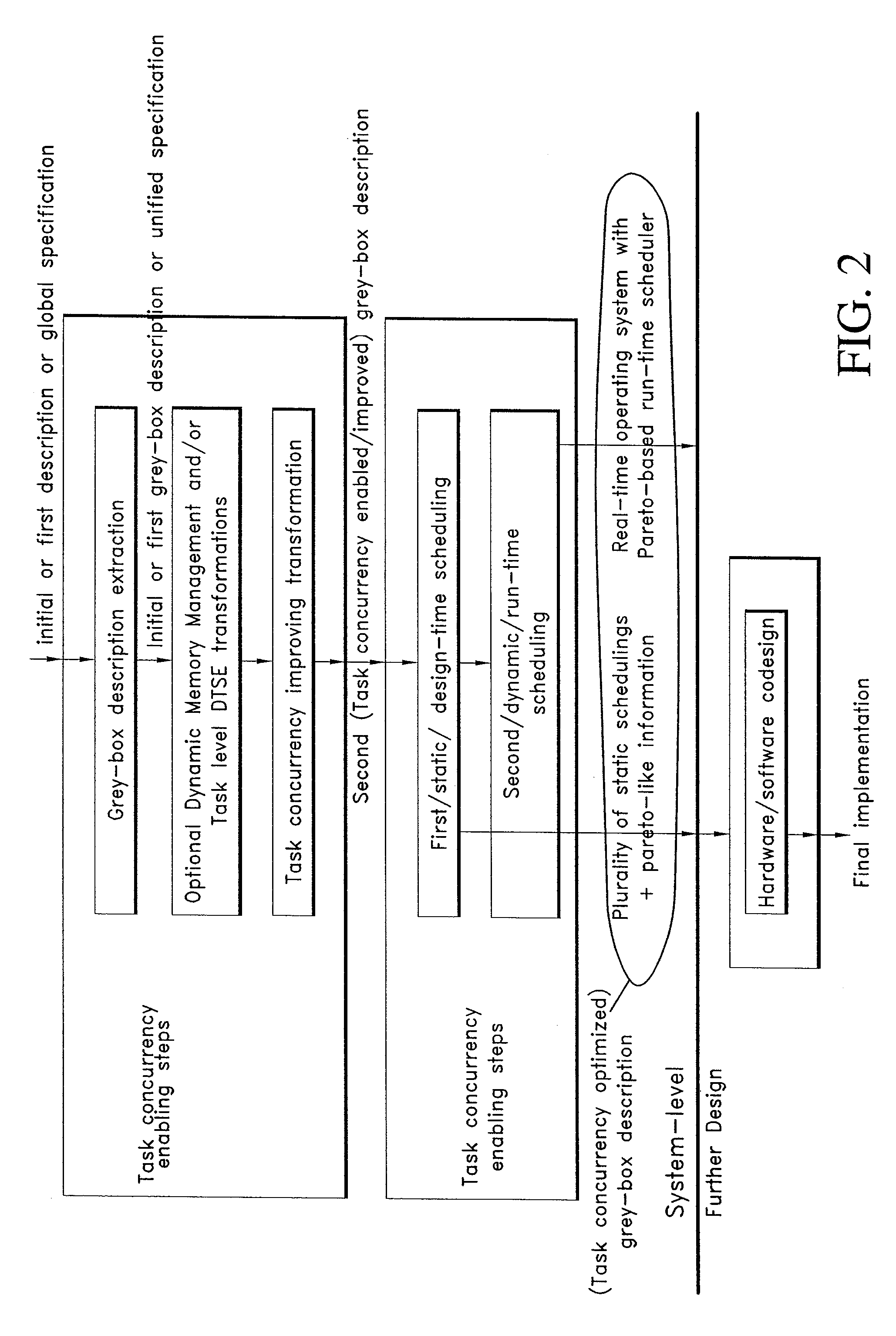
[0028]Hence said task concurrency optimization, and in particular the static or design-time scheduling part thereof, performs a pre-ordering within tasks under real-time constraints while minimizing processor operation costs.

Problems solved by technology

So hiding of concurrency is most often due to data dependencies.

Method used


Image

  • Task concurrency management design method
  • Task concurrency management design method
  • Task concurrency management design method

Examples


case 1

[0242]

[0243]Conditions:

[0244]1. TB=1 symbol period;

[0245]2. VLOW=1V, VHIGH=3V;

[0246]3. The two timers and SW threads are scheduled independently.

[0247]The Eq. CS,i in Tab. 5 is the equivalent execution time on the 10 MHz processor.

[0248]The optimal schedule result derived from the ILP solver is shown in Tab. 6. It is interesting to notice that though task 4 and task 12 have the same execution time, the scheduling result and energy consumed are quite different because of their different deadlines. For a stricter deadline, more part of the thread frame will be executed on the higher voltage processor and that means more power. Task 7 and task 14 also have the same execution time but different scheduling.

case 2

[0249]

[0250]Conditions:

[0251]1. TB=1 symbol period;

[0252]2. VLOW=1V, VHIGH=3V;

[0253]3. The two timers are grouped together.

[0254]The difference between case 1 and case 2 can be seen in FIG. 36, where the shadowed areas represent the processor time occupied by the DSTU thread nodes. In case 2, the two timers are integrated in one group and scheduled as a unit. Though there is idle time in that group, it is not available to the processes outside that group. The optimal schedule result derived from the ILP solver is shown in Tab. 8.

case 3

[0255]

[0256]Conditions:

[0257]1. TB=2 symbol periods;

[0258]2. VLOW=1V, VHIGH=3V;

[0259]3. The two timers are grouped together for two symbols.

[0260]All possible schedules of the timers in two symbol periods that make a reasonable distinction can be found in FIG. 37. The optimal schedule result derived from the ILP solver is shown in Tab. 10.


PUM


Abstract

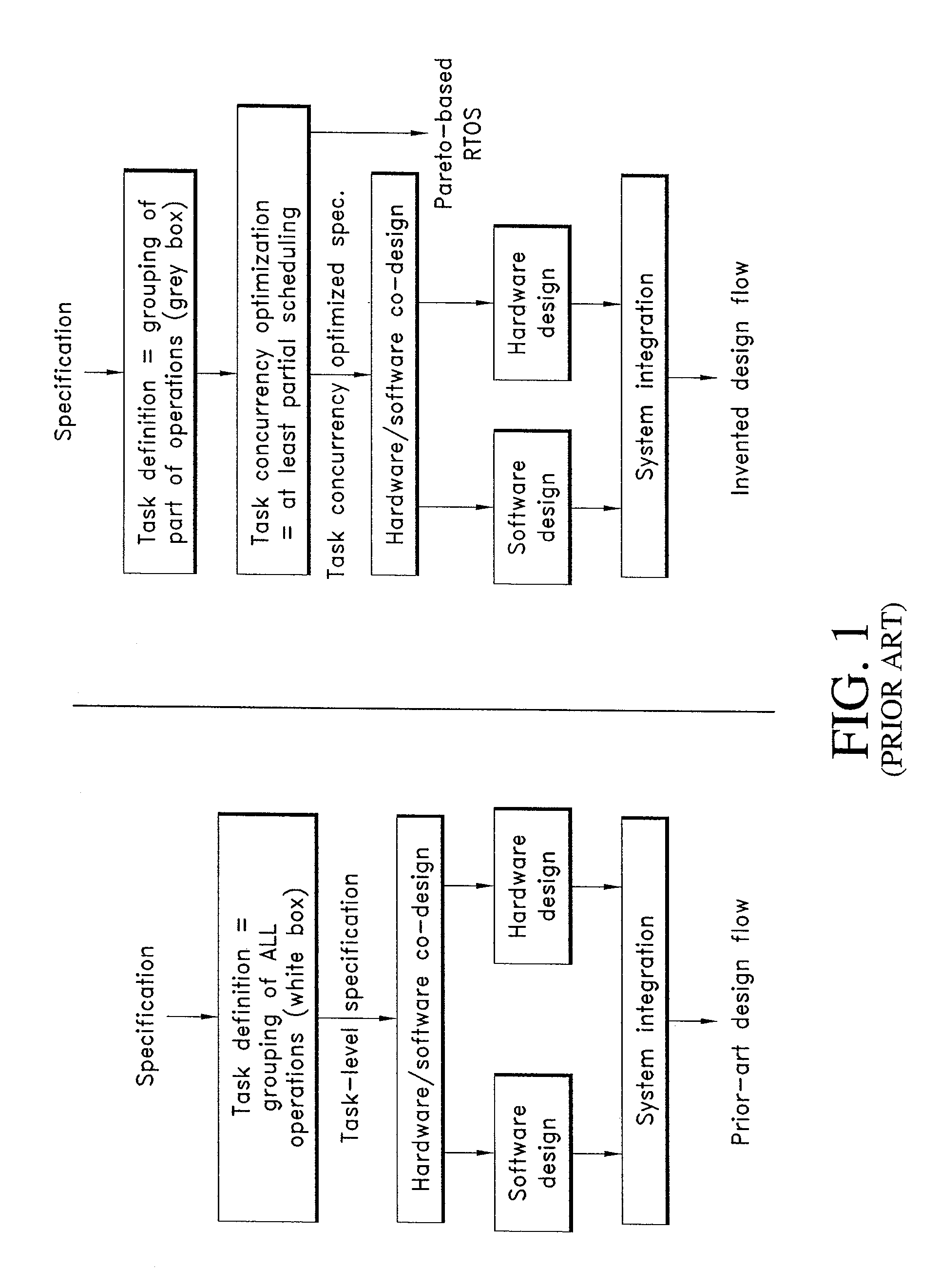
A system and method of designing digital system. One aspect of the invention includes a method for designing an essentially digital system, wherein Pareto-based task concurrency optimization is performed. The method uses a system-level description of the functionality and timing of the digital system. The system-level description comprises a plurality of tasks. Task concurrency optimization is performed on said system-level description, thereby obtaining a task concurrency optimized system-level description, including Pareto-like task optimization information. The essentially digital system is designed based on said task concurrency optimized system-level description. In one embodiment of the invention, the description is includes a “grey-box” description of the essentially digital system.

Description

RELATED APPLICATION[0001]This application claims priority to and incorporates by reference, in its entirety, U.S. Provisional Patent Application No. 60 / 227,339, filed Aug. 23, 2000.FIELD OF INVENTION[0002]The invention relates to system level hardware-software codesign method especially including the management of concurrent tasks.BACKGROUND OF THE INVENTION[0003]Semiconductor processing technology nowadays allows complex systems to be integrated on one single chip. A consistent system design technology is in great need to cope with such complexity and with the ever shortening time-to-market requirements (B. Tuck Raise your sights to the system level—design report: '97 Paris forum (round-table discussion). Computer Design, pp. 53-74, June 1997.). It should allow to map these applications cost-efficiently to the target realisation while meeting all real-time and other constraints.[0004]The target applications of our task-level system synthesis approach are advanced real-time multi-me...

Claims


Application Information

Patent Timeline
IPC IPC(8): G06F17/50
CPCG06F17/5045G06F2217/86G06F30/30G06F2117/08
Inventor CATTHOOR, FRANCKYYANG, PENGWONG, CHUNMARCHAL, PAULPRAYATI, AGGELIKICOSSEMENT, NATHALIELAUWEREINS, RUDY
Owner INTERUNIVERSITAIR MICRO ELECTRONICS CENT (IMEC VZW)
Learn More