
Remote touch simulation systems and methods

a remote touch simulation and simulation system technology, applied in the field of remote touch simulation systems and methods, can solve the problems of inability to accurately detect the touch screen, the operation fitness of the touch screen sensor can change, and the conventional evaluation and repair approach is both costly and time-consuming. it is possible to improve the diagnostic, calibration and maintenance capabilities, and improve the diagnostic and calibration efficiency. the effect of tim

Inactive Publication Date: 2007-06-26
3M INNOVATIVE PROPERTIES CO
View PDF18 Cites 51 Cited by
  • Summary
  • Abstract
  • Description
  • Claims
  • Application Information

AI Technical Summary

Benefits of technology

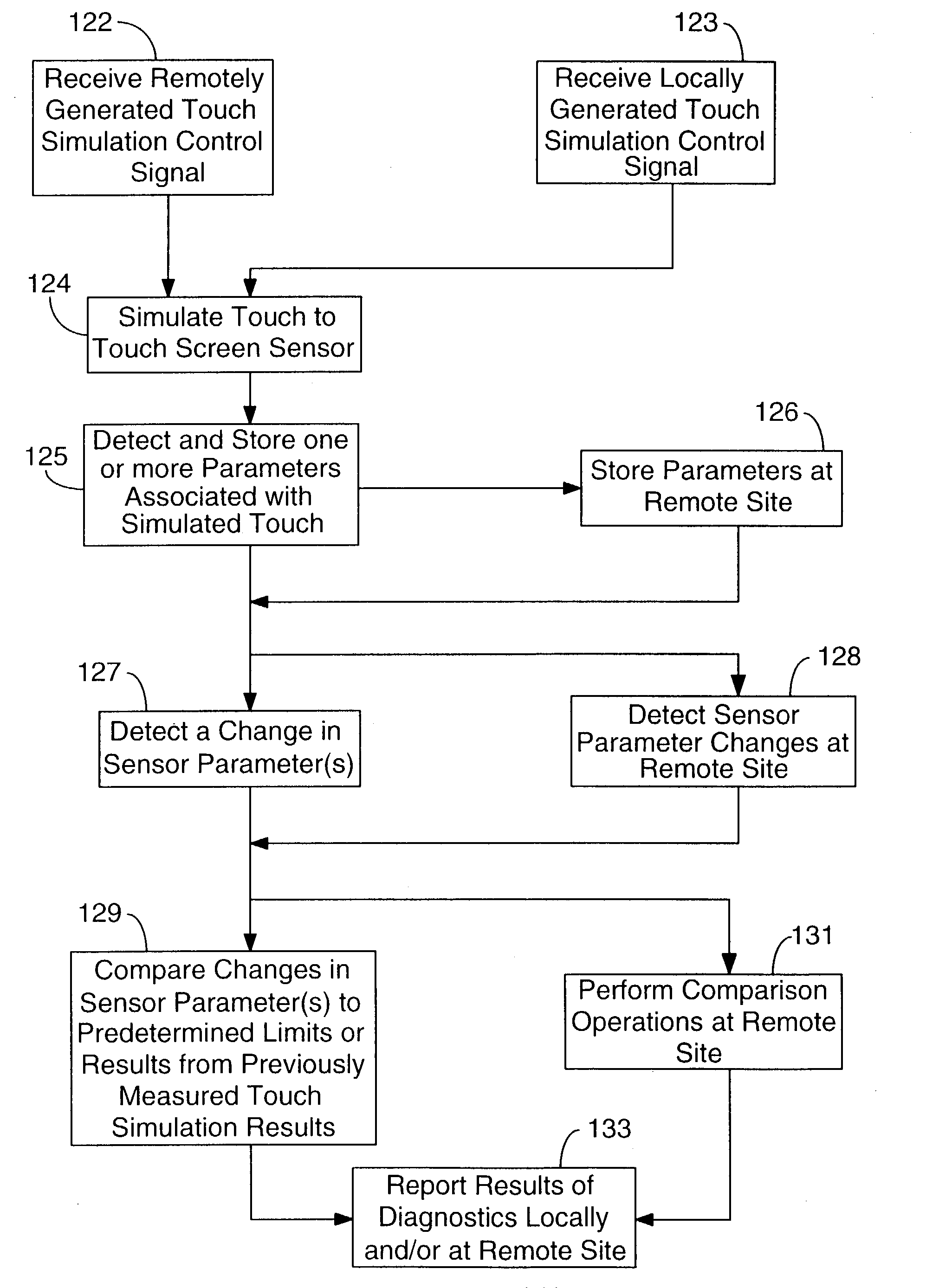
[0005]Remote touch simulation is typically employed for purposes of performing various types of diagnostics, calibration, and repair procedures, for example. Touch simulation can involve processes performed at a remote site, such as initiating, monitoring, analyzing, or controlling a touch simulation process. Results of a procedure involving touch simulation, such as current and historical touch detection accuracy data, can be acquired and used locally or remotely to assess the operational fitness of the touch screen sensor over time. Touch simulation methodologies implemented in accordance with the principles of the present invention provide for enhanced diagnostic, calibration, and maintenance capabilities that can be used across a number of differing touch screen sensor technologies, including, for example, capacitive, resistive, non-capacitive force, active or passive acoustic, and infrared touch screen sensor technologies.

Problems solved by technology

Touch detection accuracy of the touch screen can change over time due to a number of system and environmental reasons, such as wear during extended use.
Such conventional evaluation and repair approaches are both costly and time inefficient.
As use of touch screen systems becomes more widespread, particularly in networked applications involving dozens, hundreds, or even thousands of such systems, conventional on-site monitoring, testing, and servicing approaches will become increasingly expensive and less practical to implement.

Method used


Image

  • Remote touch simulation systems and methods
  • Remote touch simulation systems and methods
  • Remote touch simulation systems and methods

Examples


Embodiment Construction

[0036]In the following description of the illustrated embodiments, reference is made to the accompanying drawings which form a part hereof, and in which is shown by way of illustration, various embodiments in which the invention may be practiced. It is to be understood that the embodiments may be utilized and structural changes may be made without departing from the scope of the present invention.

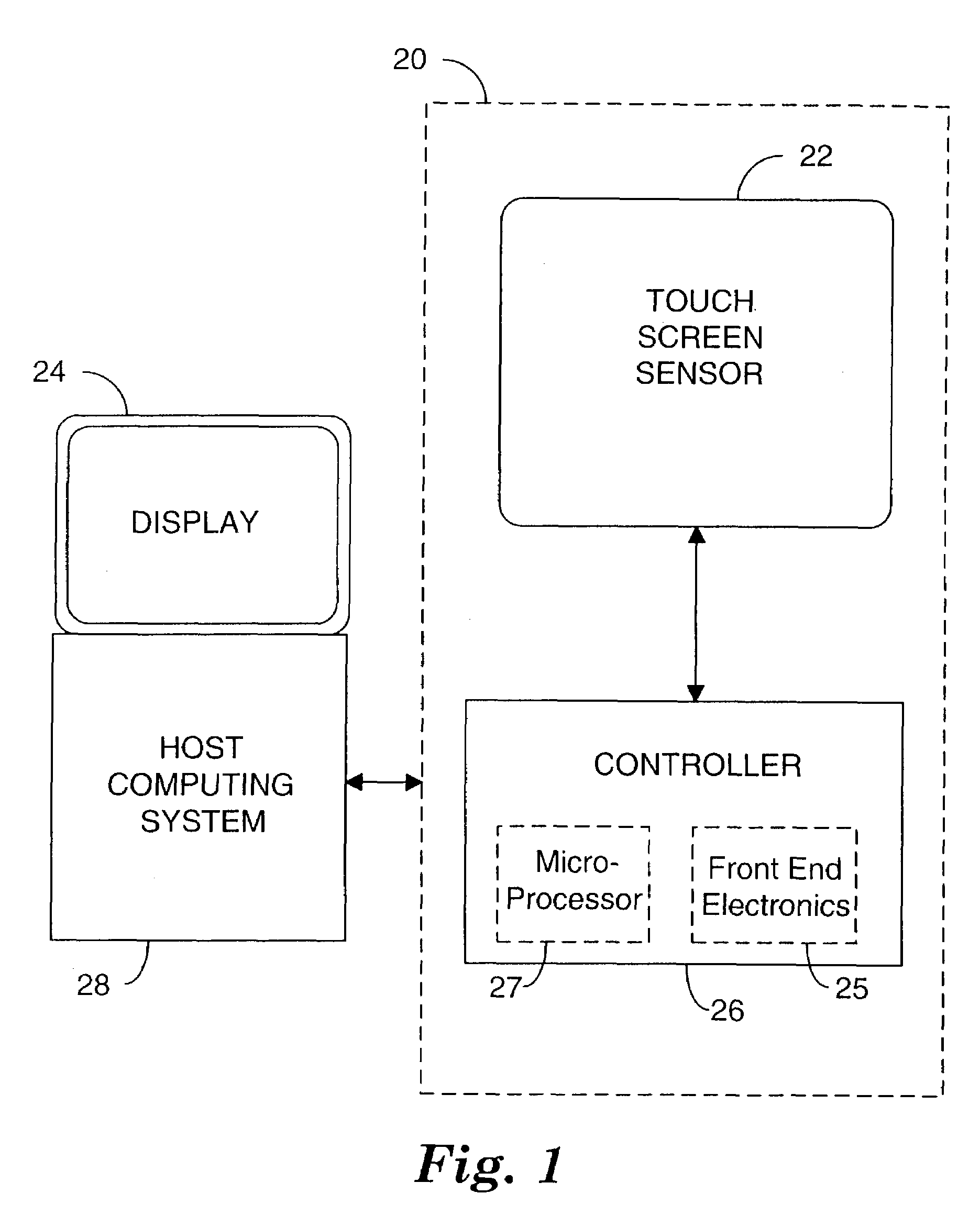
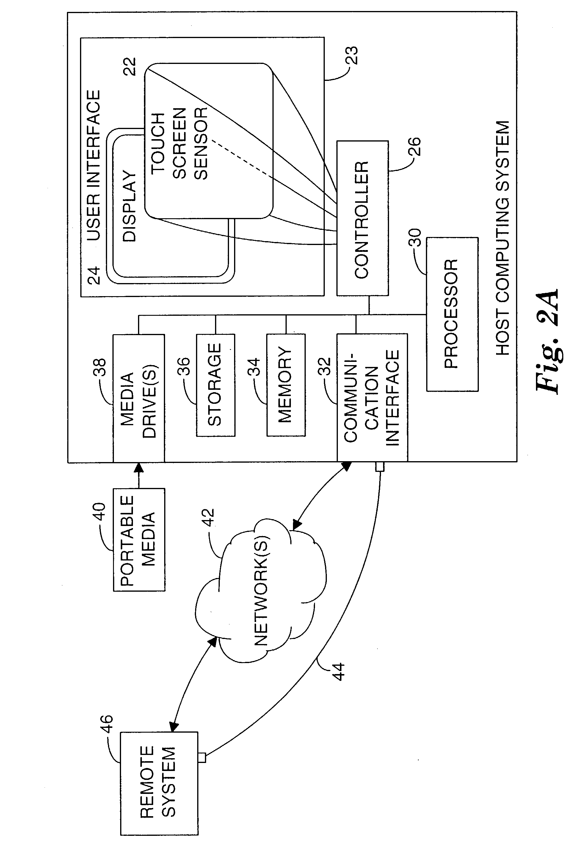
[0037]The present invention is directed to systems and methods for simulating a touch on a touch screen sensor which involve interaction between a remote system and a touch screen system (TSS) which incorporates the touch screen sensor or a local processor coupled to the TSS. Systems and methods of the present invention are also directed to cooperative operation between a TSS and a remote system for purposes of performing monitoring, diagnostic, calibration, and / or servicing operations, which may or may not involve touch simulation.

[0038]Various embodiments of the present invention provide ...


PUM


Abstract

Systems and methods provide for simulating an effective human touch on a touch screen sensor of a touch screen system. Touch simulation involves interaction with, or cooperation between, a subject touch screen system and a remote system via a communication or network link. Remote touch simulation typically involves establishing a communication link between the touch screen system and a remote location, simulating a touch to the touch screen sensor, and communicating data associated with simulating the touch between the touch screen system and the remote location via the communication link. Remote touch simulation can be employed to perform various types of diagnostics, calibration, and repair procedures.

Description

FIELD OF THE INVENTION[0001]The present invention relates generally to touch screen systems and, more particularly, to systems and methods for effecting remote simulation of an effective human touch on a touch screen sensor.BACKGROUND OF THE INVENTION[0002]A typical touch screen employs a sheet of glass with a conductive coating, such as indium tin oxide, with four corner terminal connections. The touch screen may be configured as a capacitive or resistive touch screen, with a pattern of electrodes made of conductive material. A finger, stylus, or conductive top sheet can draw or inject current at the point of contact. The current can then distribute to the touch panel terminals in a proportionate manner relative to the location of the point of contact.[0003]Touch detection accuracy of the touch screen can change over time due to a number of system and environmental reasons, such as wear during extended use. Monitoring, testing, and servicing of touch screen systems has conventional...

Claims


Application Information

Patent Timeline
IPC IPC(8): G09G5/00G06FG06F3/033G06F3/044G06F3/048G06F9/455
CPCG06F3/044G06F3/0488G06F3/0445G06F3/0418G06F3/0428G06F9/455G06F2203/04107G06F3/04162G06F3/0446
Inventor GEAGHAN, BERNARD O.TAYLOR, GORDON F.
Owner 3M INNOVATIVE PROPERTIES CO
Learn More