Load lock chamber, processing system

a technology of processing system and lock chamber, which is applied in the direction of thin material processing, printers, instruments, etc., can solve the problems of gas temperature drop, wafer temperature drop exceeding the temperature stability budget required, particle adhesion to the wafer, etc., and achieves high-quality processing and reduces the temperature drop of the wafer

Inactive Publication Date: 2007-06-26
CANON KK
View PDF11 Cites 8 Cited by
  • Summary
  • Abstract
  • Description
  • Claims
  • Application Information

AI Technical Summary

Benefits of technology

[0020]Accordingly, it is an exemplified object of the present invention to provide a load lock chamber, and a processing system, which maintain predetermined throughput, reduces temperature drops of a wafer caused by adiabatic expansions and particles' adhesions to the wafer in exchanging an atmosphere, and provides high-quality processing.

Problems solved by technology

A replacement of the load lock chamber with a vacuum atmosphere has two significant problems: Firstly, while the gas is being exhausted from the load lock chamber, the gas's temperature drop due to the adiabatic expansion cools a wafer that contacts gas.
The wafer's temperature drop exceeds its temperature stability budget required in the exposure.
The other problem is adhesions of particles to the wafer.
More specifically, the exhaustion blows particles up in exchanging an atmosphere in the load lock chamber, causing them to adhere to the wafer.
Disadvantageously, the particles adhered wafer does not accept high-quality processes.
In addition, the long exhaust time extends the heat exchange time between the process chamber and the gas, and gas's temperature drop.
However, indeed the gas contacts walls of the load lock chamber, receives heat, and does not exhibit a complete adiabatic expansion.
However, the slow exhaustion naturally delays a completion of exhaustion.
In other words, the above methods do not sufficiently take care of the throughput deterioration.
While the above time limits are to maintain the throughput and to replace the atmosphere in the load lock chamber, the time periods, such as maximum 60 [s] for a replacement of the atmosphere in the load lock chamber, which includes 25 [s] to 30 [s] for an gas exhaustion and 10 to 15 [s] for a gas supply, are not sufficient for disadvantageous particles' blowing up and gas's temperature drop.

Method used


Image

  • Load lock chamber, processing system
  • Load lock chamber, processing system
  • Load lock chamber, processing system

Examples


Embodiment Construction

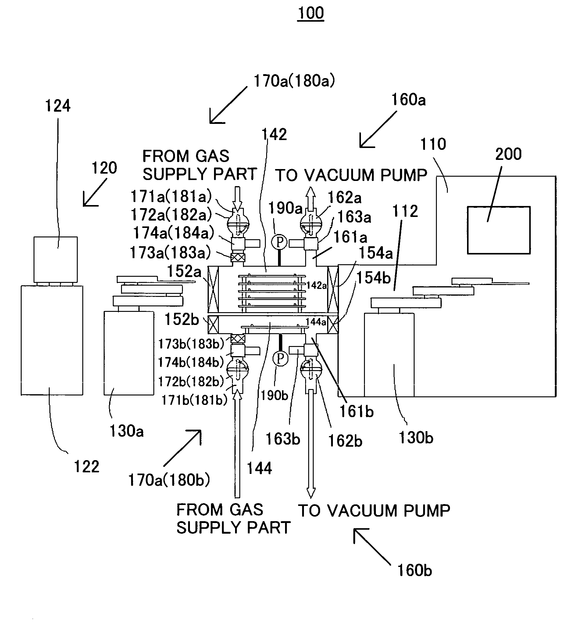
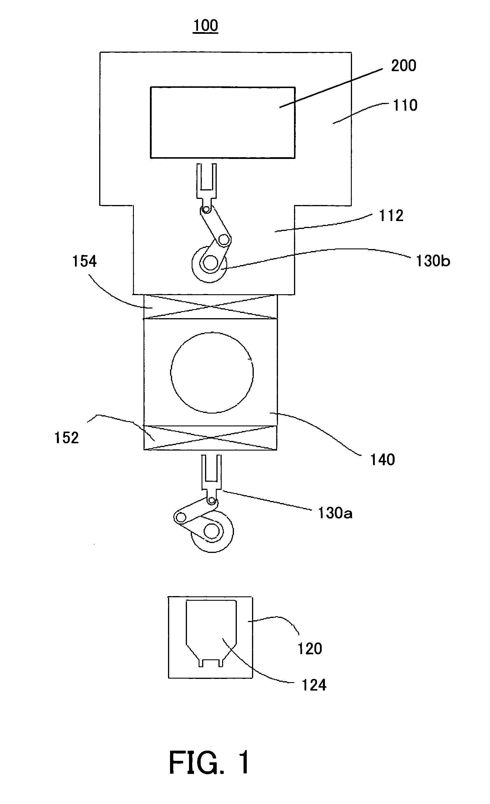
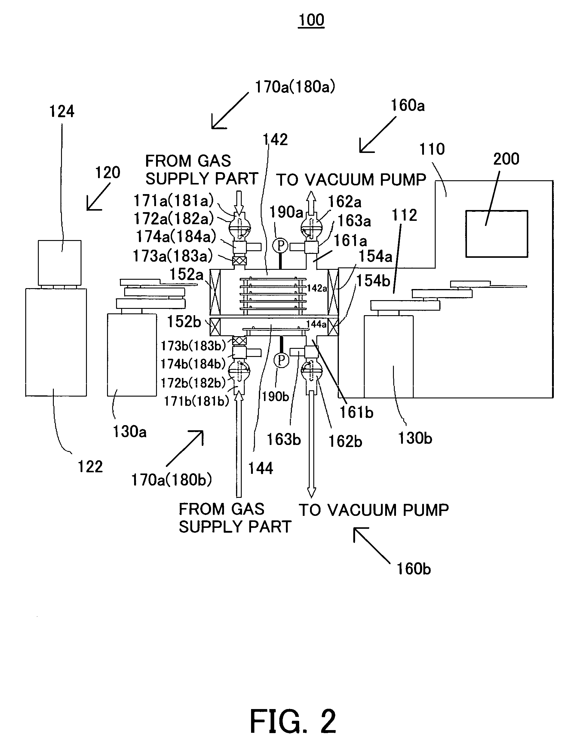
[0033]A description will now be given of a processing system 100 as one aspect of the present invention with reference to the accompanying drawings. The same reference numeral in each figure denotes the same element, and a description thereof will be omitted. Here, FIG. 1 is a schematic block diagram of the processing system 100. FIG. 2 is a schematic block diagram of a detailed structure of the processing system 100.

[0034]While the processing system 100 of the instant embodiment exposes a wafer as an object to be exposed, the present invention does not limit the process by the processing apparatus to exposure. Of course, the exposure process is suitable for the present invention since the exposure process requires high throughput as discussed above.

[0035]The processing system 100 includes, as shown in FIG. 1, a process chamber 110, a preliminary chamber 112, a port 120, a first transport means 130a, a second transport means 130b, a load lock chamber 140, a first gate valve 152 (tha...


PUM


Abstract

A load lock chamber provided between a port that accommodates an object to be processed and is maintained at an ambient pressure, and a process chamber that is maintained at a reduced pressure or vacuum environment and performs a predetermined process for the object, said load lock chamber replacing an atmosphere in said load lock chamber and delivering the object between the port and the process chamber includes a first load lock chamber that includes a first holder for holding the object received from the port, and a second load lock chamber that includes a second holder for holding the object received from the process chamber, wherein the first holder holds more objects than the second holder.

Description

[0001]This application claims a benefit of priority based on Japanese Patent Application No. 2003-060566 filed on Mar. 6, 2003, which is hereby incorporated by reference herein in its entirety as if fully set forth herein.BACKGROUND OF THE INVENTION[0002]The present invention relates generally to a load lock chamber, and more particularly to a load lock chamber for use with a fabrication process of a semiconductor substrate, a liquid crystal display (“LCD”) plate, etc., which transports an object, such as a semiconductor substrate and an LCD, from a port as a supply part to a process chamber that provides an exposure process etc., and replaces an atmosphere between the ambient pressure and a reduced pressure environment. The present invention is also directed to a processing system having this load lock chamber.[0003]Recent demands for smaller and lower profile electronic apparatuses have increasingly sought for finer semiconductor devices to be mounted onto these electronic apparat...

Claims


Application Information

Patent Timeline
Patent Type & Authority Patents(United States)
IPC IPC(8): G03B27/42G03B27/32G03B27/58G03B27/62H01L21/027H01L21/677
CPCH01L21/67748Y10S414/138Y10S414/135Y10S414/139
Inventor EDO, RYO
Owner CANON KK
Why Eureka
Try Eureka