Synchronising circuit

a synchronising circuit and circuit technology, applied in the field of synchronising circuits, can solve the problem of less accurate phase of data of that channel, and achieve the effect of avoiding the loss of data

Active Publication Date: 2007-06-26
TEXAS INSTR INC
View PDF5 Cites 3 Cited by
  • Summary
  • Abstract
  • Description
  • Claims
  • Application Information

AI Technical Summary

Benefits of technology

[0014]An alternative solution is to wait until a suitable time has expired without any data transitions of the data channel and to then move (or “nudge”) the phase of the data channel by a small amount around the phase wheel in the direction of the phase of the clock channel. This approach has the advantage of not significantly changing the estimated phase of the data channel by a large

Problems solved by technology

The longer the period of time since the previous data transition on a given data channel, the less accurate the phase of the

Method used


Image

  • Synchronising circuit
  • Synchronising circuit
  • Synchronising circuit

Examples


Embodiment Construction

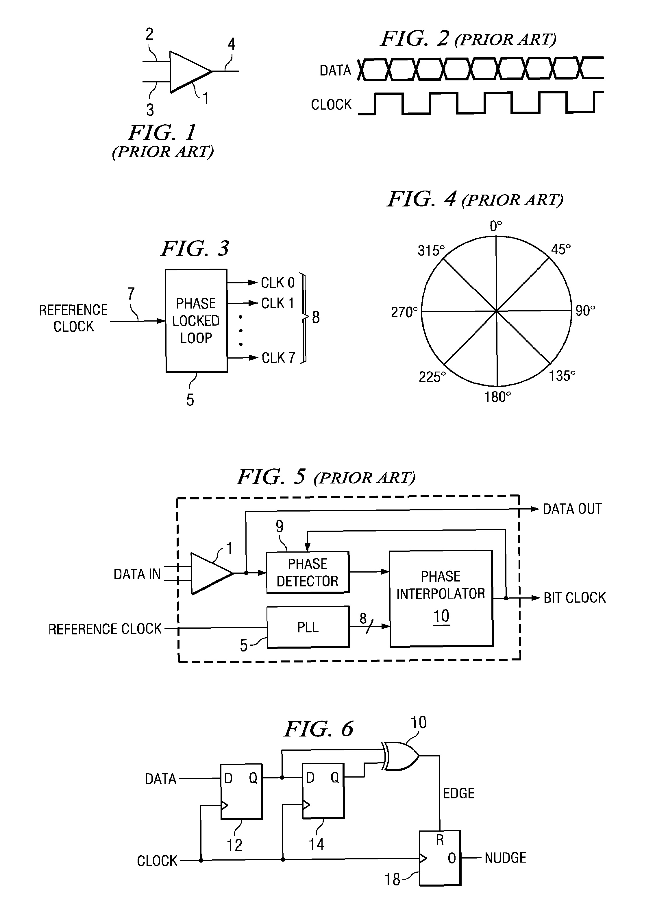
[0075]FIG. 6 shows a circuit that can be used to implement the nudge function described above. The circuit includes flip-flops 12 and 14, exclusive-OR (XOR) gate 16 and counter 18. Flip-flops 12 and 14 and XOR gate 16 are used as an edge detector. The data signal of the relevant data channel is coupled to the D-input of flip-flop 12 and the Q-output of flip-flop 12 is coupled to the D-input of flip-flop 14. The Q-outputs of flip-flops 12 and 14 are respectively coupled to first and second inputs of XOR gate 16, the clock inputs of flip-flops 12 and 14 and counter 18 are coupled to a CLK input and the output of the XOR gate provides an EDGE signal, which is coupled to the reset input R of the counter. The counter is provided with an overflow output O so that each time the counter overflows, a nudge signal is provided.

[0076]The CLK input may be a bit-clock, both positive and negative edges being used or, alternatively, a double-rate clock, only positive edges being used.

[0077]The nudg...


PUM


Abstract

In an integrated circuit receiving multiple serial data streams in parallel, a local clock is generated from each data stream and is synchronized with the data stream. Sometimes a data stream may have no transitions making it difficult to keep the clock synchronized with its data. A clock channel is provided, which always has edges. A circuit is provided for each data stream which measures the time elapsed since the data stream had an edge. After a certain period, the phase of the local clock is nudged towards that of the clock channel. Thereafter, the longer there are no edges on the data stream the more frequently nudges towards the phase of the clock channel are made.

Description

FIELD OF THE INVENTION[0001]The present invention relates to the detection of the phase of one or more data streams and more particularly to the generation of an approximation to the phase during a period when there are no data transitions in the data stream.BACKGROUND OF THE INVENTION[0002]FIG. 1 shows a differential driver 1 that takes a differential input on conductors 2 and 3 and converts that input into a serial data stream on an output conductor 4.[0003]It is known to use the differential driver 1 of FIG. 1 as an input stage to a digital system. It is also known to generate a clock signal for the digital system from the data stream on the output 4 of the differential driver 1.[0004]FIG. 2 shows a single data stream and an associated clock signal. The clock signal shown in FIG. 2 samples the data on both the rising and falling clock edges and the clock transitions are closely aligned with the mid-point of data transitions. Such alignment is preferable as the data is given the m...

Claims


Application Information

Patent Timeline
IPC IPC(8): H04L25/00H03D3/24H04L7/00H04L25/14
CPCH04L7/0008H04L7/0083H04L25/14H04L7/0025
Inventor WARD, RICHARDSURACE, GIUSEPPEJOY, ANDREW
Owner TEXAS INSTR INC
Why Eureka
Try Eureka