Projectile for an electrical discharge weapon

a projectile and electrical discharge technology, applied in the field of electric discharge weapons, can solve the problems of sacrificing the minimum and maximum range of the muscle cells, the charge and ground darts cannot be spread at closer ranges enough to ensure, and the muscle cells are difficult to decipher the original signals, etc., to achieve low power consumption, high power efficiency, and low weight

Active Publication Date: 2007-07-03
VIEVU +1
View PDF45 Cites 71 Cited by
  • Summary
  • Abstract
  • Description
  • Claims
  • Application Information

AI Technical Summary

Benefits of technology

[0008]The present invention relates to a system and / or an associated method for providing an electrical discharge weapon and / or a method for using the same that includes a shock circuit having a low power consumption, a high power efficiency, and / or a low weight. In one embodiment, the electrical discharge weapon includes a high efficiency circuit that would reduce the weights of shock circuits while providing a more effective and safer power level, so that the circuits may be entirely contained in a projectile of the weapon and the need for range limiting trailing wires can be eliminated.

Problems solved by technology

The brain's original signals are mixed in with random noise, making it very difficult for the muscle cells to decipher the original signals.
However, a disadvantage to such a design of using two wired darts is that both minimum and maximum range are sacrificed.
That is, as known to those skilled in the art, depending on the angle between the weapon's bores, the charge and ground darts will not spread enough at closer ranges to insure an adequately large current path through the target, unless the marksman is lucky enough to impact a particularly sensitive area of the body.
In addition, the wired darts could not pass down the bore of most conventional firearms.
Moreover, if the wires are not deployed to their maximum range and length, they will hang from the cartridge over the bottom of the port or firing bay and frequently rest laxly on the ground in close proximity to each other or even resting upon or overlapping each other for portions of their lengths.
The weight of the insulation further limits the range of the darts and the type of firearms that can project these darts.

Method used


Image

  • Projectile for an electrical discharge weapon
  • Projectile for an electrical discharge weapon
  • Projectile for an electrical discharge weapon

Examples


Embodiment Construction

[0029]In the following detailed description, only certain exemplary embodiments of the present invention are shown and described, by way of illustration. As those skilled in the art would recognize, the described exemplary embodiments may be modified in various ways, all without departing from the spirit or scope of the present invention. Accordingly, the drawings and description are to be regarded as illustrative in nature, and not restrictive.

[0030]There may be parts shown in the drawings, or parts not shown in the drawings, that are not discussed in the specification as they are not essential to a complete understanding of the invention. Like reference numerals designate like elements.

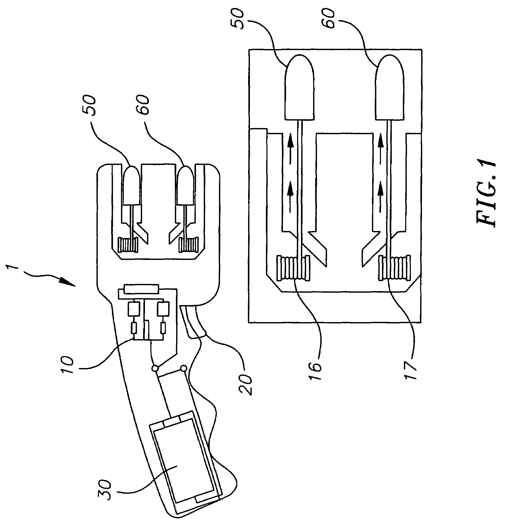
[0031]Referring to FIG. 1, an example of an electrical discharge weapon is shown which includes a housing 1, a shock circuit 10, a trigger 20, battery or batteries 30, a first electrically conductive dart 50, and a second electrically conductive dart 60. Each of the darts 50, 60 is connected to the ...


PUM


Abstract

An electrical discharge weapon projectile for immobilizing a live target that includes a shock circuit having a low power consumption, a high power efficiency, and / or a low weight. In one embodiment, the projectile includes a high efficiency circuit that would reduce the weights of shock circuits while providing a more effective and safer power level, so that the circuits may be entirely contained within the projectile to eliminate the need for range limiting trailing wires.

Description

FIELD OF THE INVENTION[0001]The present invention relates generally to the field of an electrical discharge weapon for immobilizing a live target. More specifically, the present invention is related to an electrical discharge weapon having an improved shock circuit and a method for operating the same.BACKGROUND OF THE INVENTION[0002]Electrical discharge weapons are weapons that connect a shocking power to a remote live target by means of darts and / or trailing wires fired from the electrical discharge weapons. The shocks debilitate violent suspects, so peace officers can more easily subdue and capture them. Stun guns, by contrast, connect the shocking power to the live target that are brought into direct contact with the stun guns to subdue the target. Electrical discharge weapons and guns are far less lethal than other more conventional firearms.[0003]In general, the basic idea of the above described electrical discharge weapon s is to disrupt the electric communication system of mu...

Claims


Application Information

Patent Timeline
Patent Type & Authority Patents(United States)
IPC IPC(8): F41C9/00F41B15/04F42B12/00F42B30/00
CPCF41H13/0025F41H13/0031
Inventor KEELY, WILLIAM ARTHURMCNULTY, JR., JAMES F.
Owner VIEVU
Why Eureka
Try Eureka