Vehicle canister arranging structure

a technology of canisters and canisters, which is applied in the direction of liquid fuel feeders, machines/engines, transportation and packaging, etc., can solve the problems of complicated configuration of fuel tanks, difficult to secure large fuel tank capacity, etc., and achieve good efficiency, good efficiency, good efficiency

Inactive Publication Date: 2007-07-03
HONDA MOTOR CO LTD
View PDF15 Cites 36 Cited by
  • Summary
  • Abstract
  • Description
  • Claims
  • Application Information

AI Technical Summary

Benefits of technology

[0020]Incidentally, in order to release fuel vapor from activated charcoal granules with good efficiency, it is preferable to keep activated charcoal granules at a certain temperature. Then, according to the second aspect of the present invention, by forming part of the exhaust pipe into the expansion chamber, the expansion chamber can be arranged in the vicinity of the canister. Since the outside diameter of an outer circumference of the expansion chamber is large, a large outer circumferent

Problems solved by technology

Thus, the recessed accommodating portion 103 must be formed in the fuel tank 102 and this arranging structure mak

Method used


Image

  • Vehicle canister arranging structure
  • Vehicle canister arranging structure
  • Vehicle canister arranging structure

Examples


first embodiment

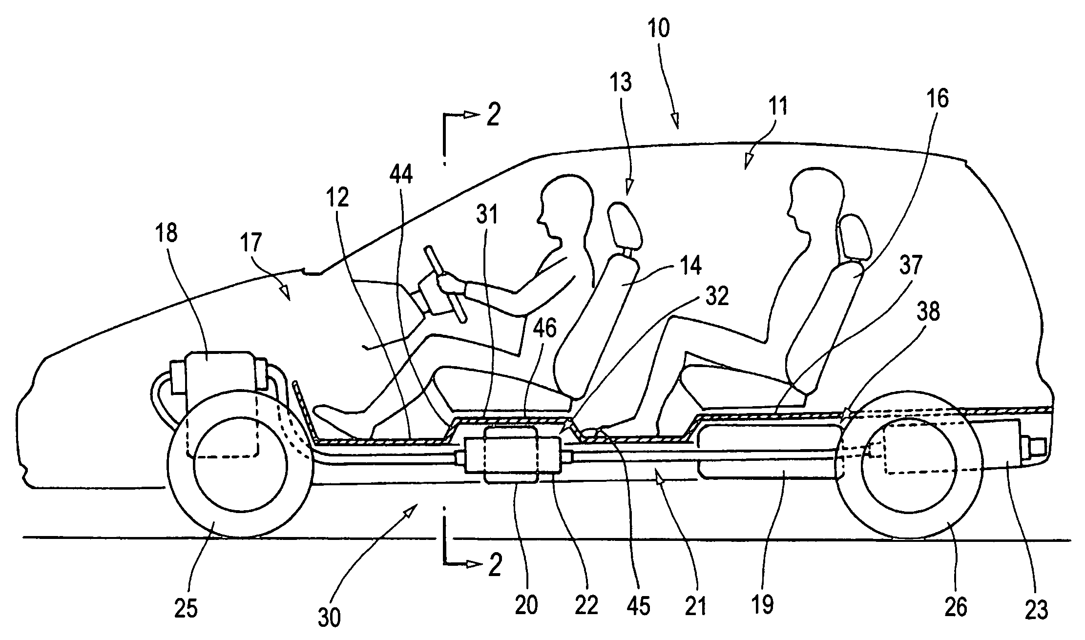
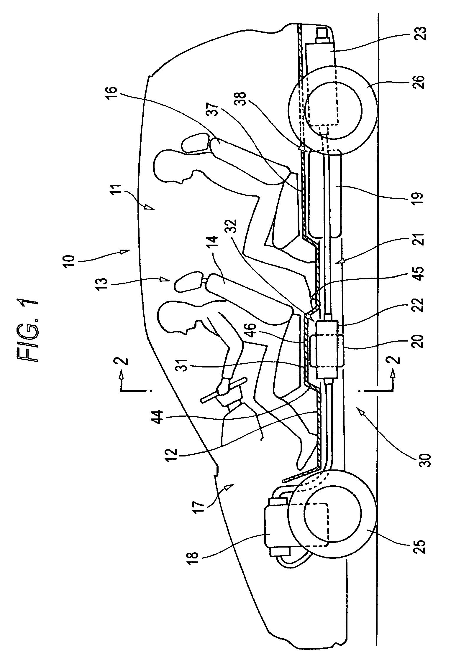
[0032]FIG. 1 is an explanatory drawing of a vehicle having a vehicle canister arranging structure (a first embodiment) according to the present invention.

[0033]In the following description, the first end is the rear of the vehicle and the second end is the front of the vehicle. The fuel reservoir or tank is arranged under the rear seat. The exhaust pipe constitutes an expansion chamber.

[0034]A vehicle 10 is such that a front seat 13 including a driver's seat 14 and a front passenger seat 15 (refer to FIG. 2) and a rear seat 16 are provided in a passenger compartment 11 above a floor panel 12 which constitutes a floor surface of the passenger compartment 11, an engine 18 is installed in an engine compartment 17 situated in front of the passenger compartment 11, and a fuel tank 19, a canister 20 and an exhaust pipe 21 are arranged under the floor panel 12. Note that reference numeral 25 denotes a front wheel and reference numeral 26 denoting a rear wheel.

[0035]Hereinafter, an arrangin...

second embodiment

[0063]FIG. 5 is a sectional view of a vehicle provided with a vehicle canister arranging structure (a second embodiment) according to the present invention.

[0064]A vehicle canister arranging structure 60 according to a second embodiment of the present invention is such that a front passenger seat location 34 of a floor panel 12 is expanded toward a passenger compartment 11 so as to be formed substantially into a rectangular shape as viewed from the top to thereby constitute a second recessed accommodating portion 35, so that an expansion chamber 22 constituting part of an exhaust pipe 21 is accommodated in the second recessed accommodating portion 35 so formed, and an intermediate location 61 of the floor panel 12 which corresponds to a space between the driver's seat 14 and the front passenger seat 15 is expanded toward the passenger compartment 11 so as to be formed substantially into a rectangular shape to thereby constitute a third recessed accommodating portion 62, so that a ca...

third embodiment

[0067]FIG. 6 is a sectional view of a vehicle provided with a vehicle canister arranging structure (a third embodiment) according to the present invention.

[0068]A vehicle canister arranging structure 70 according to a third embodiment of the present invention is such that, of a floor panel 12, any two locations selected from a driver's seat location 31, a front passenger seat location 34, and an intermediate location 61 which corresponds to a space between the driver's seat 14 and the front passenger seat 15, as an example thereof, the front passenger seat location 34 and the intermediate location 61 are expanded together toward a passenger compartment 11 so as to constitute a fourth recessed accommodating portion 72, so that a canister 20 and an expansion chamber 22 constituting part of an exhaust pipe 21 are accommodated in the fourth recessed accommodating portion 72.

[0069]According to the vehicle canister arranging structure 70 of the third embodiment, an advantage similar to th...


PUM


Abstract

A vehicle having a passenger compartment, an engine arranged at a front end thereof, and a fuel tank arranged under a rear seat and the passenger compartment comprising a canister and an exhaust pipe receiving exhaust gas from the engine and outputting the exhaust gas, wherein the canister and the exhaust pipe are positioned in respective recessed accommodating portions, one of the respective recessed accommodating portions is located between the fuel tank and the engine, and below the passenger compartment.

Description

BACKGROUND OF THE INVENTION[0001]1. Field of the Invention[0002]The present invention relates to a vehicle canister arranging structure in which a fuel tank, a canister and an exhaust pipe are arranged under a floor panel constituting a floor surface of a passenger compartment.[0003]2. Description of the Related Art[0004]A canister arranging structure is known in which a fuel tank is provided under a floor surface of an automobile with a canister being provided in a corner location of the fuel tank for example, refer to Japanese Published Patent Application JP-A-11-62726 (page 3, FIG. 1)(U.S. Pat. No. 6,105,708).[0005]The related art will be described in detail by referring to FIG. 1 in JP-A-11-62726 (U.S. Pat. No. 6,105,708).[0006]FIG. 8 is a plan view of the conventional vehicle canister arranging structure. Note that the reference numerals are renewed.[0007]A conventional vehicle canister arranging structure 100 is such that a fuel tank 102 is provided under a floor panel constit...

Claims


Application Information

Patent Timeline
IPC IPC(8): B60K15/01B60K13/04B60K15/00B60K15/063B60K15/077B62D25/20F01N13/08F02M25/08F02M37/00
CPCB60K13/04B60K15/00B60K15/063B62D25/20B62D25/2036F01N13/08F01N2340/04B60K2015/03557
Inventor MATSUMOTO, HIDEKIINOUE, HIROTOKANEKO, NAOMASAORIHARA, JUNICHI
Owner HONDA MOTOR CO LTD
Why Eureka
Try Eureka