Apparatus for dispensing an atomized liquid product

a liquid product and apparatus technology, applied in the direction of liquid dispensing, rigid containers, containers, etc., can solve the problems of reducing the effect of the propellant acting as a solvent or diluent for the liquid product, affecting the flow rate of the exit port, and affecting the flow rate of the liquid product, so as to reduce the viscosity, reduce the total flow rate, and reduce the effect of the viscosity

Inactive Publication Date: 2007-07-03
BOEHRINGER INGELHEIM MICROPARTS
View PDF35 Cites 27 Cited by
  • Summary
  • Abstract
  • Description
  • Claims
  • Application Information

AI Technical Summary

Benefits of technology

[0014]It is a further object of the present invention to provide an apparatus for atomizing a liquid product the using pressure of a propellant to effectively atomize a liquid product, having a higher viscosity than for example water, into small droplets while requiring a reduced amount of propellant.
[0073]When employing the apparatus according to the invention, the liquid product containing the active ingredient can be dispensed with only a small amount or no diluent. Therefore, the liquid product is highly concentrated and very small flow rates can be achieved in comparison to conventional systems. As a consequence, the liquid product can reach for example skin without a large amount of diluents such as volatile organic compounds, resulting in a dry feel of the atomized liquid product as only little or no energy is necessary for the evaporation of volatile organic compounds. When using the atomizing apparatus according to the present invention, the flow rate of active ingredient, as defined, with only small amounts of diluents necessary for dissolving or dispersing the actual active ingredient, the flow rate of active ingredient can remain at the same level as in conventional systems, however, using a greatly reduced total flow rate of propellant and the active ingredient combined.

Problems solved by technology

In conventional systems, when liquid product is being dispensed, the effect of the propellant to act as a solvent or diluent for the liquid product is significantly reduced as the propellant changes into its gaseous phase, and becomes no longer available as a liquid solvent.
The propellant gas, the solvents and diluents are released into the atmosphere, which generates environmental problems.
With lower total flow rates, the flow at the exit port becomes unstable and discontinuous, i.e., it oscillates.

Method used


Image

  • Apparatus for dispensing an atomized liquid product
  • Apparatus for dispensing an atomized liquid product
  • Apparatus for dispensing an atomized liquid product

Examples


application examples

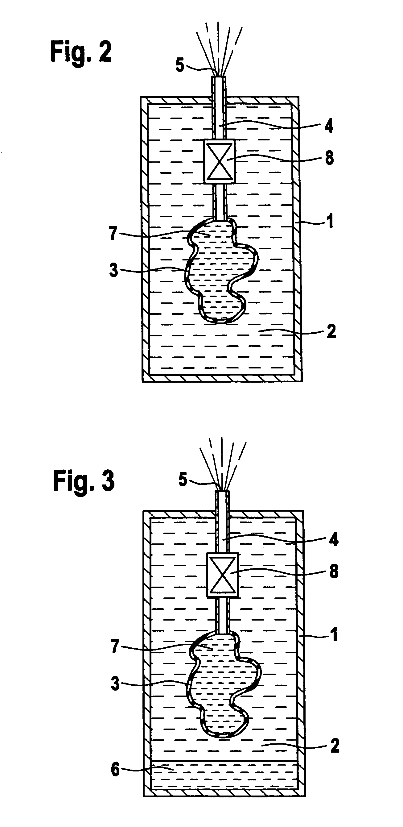
[0062]In the following, two embodiments of the apparatus according to the invention are compared for the same liquid product. The “bag-on-valve type” atomizing apparatus used a propellant, which is exchangeably compressed gas such as air or nitrogen, which does not form a liquid phase at the pressures employed, as well as liquid natural gas. The propellant is contained within a container and has access to the capillary tube atomizer via a lateral entry port of the afferent pathway, whereas the liquid product is contained within a physically separated compartment such as a collapsible bag or a cylinder with a movable piston, which compartment is connected to the afferent pathway, for example to one axial opening of an afferent tubing forming part of the afferent pathway.

[0063]The alternative embodiment, here termed “dip-tube”, employs one afferent pathway to the atomizing capillary tube, which afferent pathway does not have an additional entry port for e.g. gaseous propellant. In con...


PUM


Abstract

An apparatus for atomizing a liquid product using a propellant, which may be integrated into aerosol packs, for atomization of a liquid product. The liquid product may have a high viscosity. The total flow rate ranges from about 0.5 grams per second to about 0.01 grams per second through a single capillary tube. The liquid product is atomized within a capillary tube. The apparatus may be designed as a handheld unit or as a stationary or mobile unit using a plurality of capillary tubes.

Description

CROSS-REFERENCE TO RELATED APPLICATION[0001]This application is a divisional of U.S. patent application Ser. No. 10 / 319,571, filed on Dec. 16, 2002 now abandoned, which claims priority based upon International Patent Application No. PCT / EP02 / 08053, filed on Jul. 19, 2002, and UK Patent Application No. 0130057.3, filed on Dec. 14, 2001, all of which are herein incorporated by reference in their entirety.BACKGROUND OF THE INVENTION[0002]1. Field of the Invention[0003]The present invention relates generally to an apparatus for atomizing a liquid product which can be integrated into aerosol packs, which may be pre-pressurized. Such an apparatus may be integrated into a spray can, which is operable by simply pushing a closure mechanism to open valves for dispensing the contents of the can.[0004]2. Background of the Invention[0005]A conventional apparatus for atomizing a liquid product containing the actual active ingredient uses pressure from a propellant, which is contained within a con...

Claims


Application Information

Patent Timeline
Patent Type & Authority Patents(United States)
IPC IPC(8): B65D83/16B65D83/32B65D83/36B65D83/62B05B7/04B65D83/14
CPCB05B7/0416B65D83/62
Inventor DUNNE, STEPHEN TERENCE
Owner BOEHRINGER INGELHEIM MICROPARTS
Why Eureka
Try Eureka