Blood withdrawal system

a blood withdrawal and system technology, applied in the field of blood withdrawal system, can solve the problems of high pain of puncture, inability to meet the requirement for less painful blood withdrawal, complex construction using precisely manufactured metal parts, etc., and achieve the effect of reducing pain caused by puncture and cost-effectiveness

Active Publication Date: 2007-07-03
ROCHE DIABETES CARE INC
View PDF60 Cites 144 Cited by
  • Summary
  • Abstract
  • Description
  • Claims
  • Application Information

AI Technical Summary

Benefits of technology

[0013]In one embodiment, the present invention provides a blood withdrawal system and a method for blood withdrawal in which the described disadvantages of the prior art are avoided. The system and the method are simple. The pain caused by the puncture is reduced by a rapid drive movement of the lancet holder. The construction of the blood withdrawal system is robust and cost-effective.

Problems solved by technology

Nevertheless the puncture is frequently associated with considerable pain.
However, the use of the described systems show that in particular the requirement for a less painful blood withdrawal cannot be fulfilled.
However, the construction using precisely manufactured metal parts is complicated and involves many parts.
Another disadvantage is that the lancet emerges from the exit opening when the lancet drive is tensioned resulting in a risk of injury for the user.
A disadvantage of this prior art device is that the spring elements for driving the piston have to apply sufficient force to first destroy the wings of the piston before the piston can be moved in the lancing direction.
Furthermore if the wings are not completely destroyed, this can cause frictional effects when the piston moves within the housing in the lancing direction.
However, the wings may be damaged as a result of a strong pulling motion and this may accidentally trigger a lancing process.
Since the described mechanism is only suitable for disposable lancing devices and it is not possible to retension the lancet due to the destroyed wings on the piston, the unused lancet has to be consequently discarded.
A disadvantage of the prior art is that the rotational movement of the outer housing member makes it more difficult for the user to handle the blood withdrawal system.
The said blood withdrawal system proves to be extremely unwieldy and is very difficult to operate particularly by elderly persons.

Method used


Image

  • Blood withdrawal system
  • Blood withdrawal system
  • Blood withdrawal system

Examples


Embodiment Construction

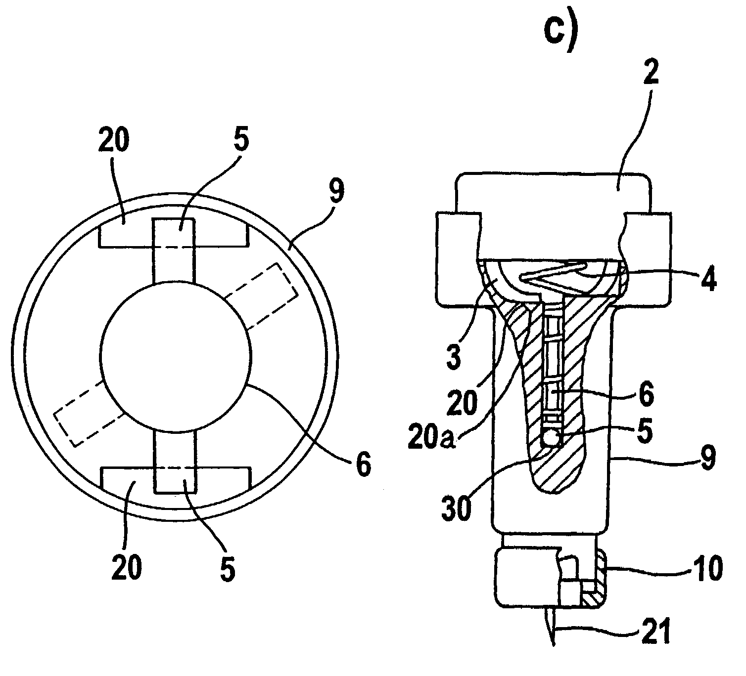
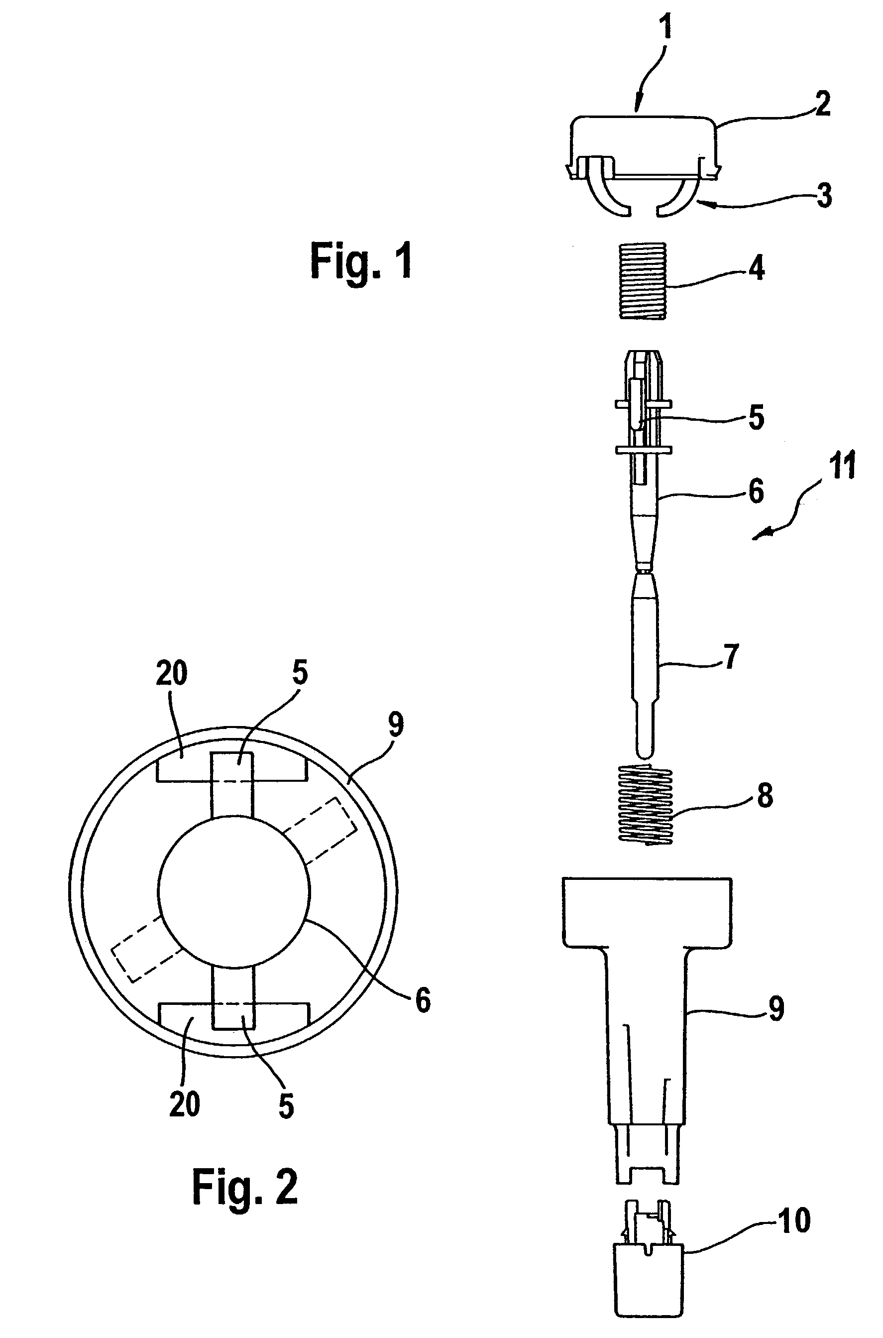
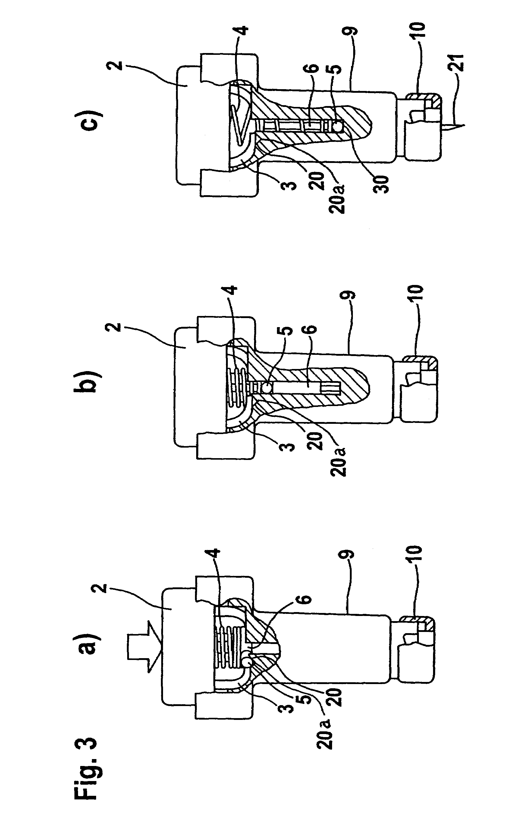
[0037]FIG. 1 illustrates the components of a blood withdrawal system before it is assembled. The blood withdrawal system is provided with a housing 9 in which the lancet holder 11 is inserted. The lancet holder 11 is movably mounted in the housing 9 such that it can carry out a lancing process along the puncturing direction. The lancet holder 11 generally includes a body 6, bearing members 5, and a sterile protector 7. For this purpose the system also comprises drive elements which are connected to and act on the lancet holder. In the example shown the drive elements are in each case a spring (4 and 8). In this connection as shown in FIG. 1, the lancet holder 11 can either rest loosely on a spring element or abut a spring element within the scope of the invention without a permanent connection between the spring element and lancet holder 11. In the sense of the invention the connection between the lancet holder 11 and a drive element is characterized in that a force is transferred f...


PUM


Abstract

A blood withdrawal system for withdrawing blood for diagnostic purposes including a lancing device having a housing with an opening and a support surface, and a lancet holder movably mounted in the opening including a lancet and a bearing member that rests on the support surface. The device further includes a trigger unit which, when moved linearly, causes a rotational movement to initiate a lancing process.

Description

FIELD OF THE INVENTION[0001]The invention concerns a blood withdrawal system for withdrawing blood for diagnostic purposes.BACKGROUND OF THE INVENTION[0002]Lancets are used in the sense of the invention as blood withdrawal systems which are used to puncture an appropriate part of the body in order to remove a small amount of blood from a part of the body for analytical or diagnostic purposes. The blood is frequently drawn from a finger or earlobe. In medical practices lancets are used for this which are inserted into an appropriate part of the body by a doctor or laboratory staff either manually or with the aid of a simple apparatus. The lancet must of course be sharp and sterile. Otherwise there are no especially stringent requirements for medical practices since blood is collected from individual patients at large time intervals and the puncture is carried out by specially trained staff. Nevertheless the puncture is frequently associated with considerable pain.[0003]If the blood w...

Claims


Application Information

Patent Timeline
Patent Type & Authority Patents(United States)
IPC IPC(8): A61B17/32A61B5/151A61B5/15
CPCA61B5/1411A61B5/150022A61B5/150183A61B5/150412A61B5/150519A61B5/150549A61B5/150717A61B5/150885A61B5/15111A61B5/15117A61B5/1513A61B5/15144H04M1/23
Inventor LIST, HANSRUSCHKE, PETERVANHIEL, BRIANKOEPPEL, BRADLEYKENNEDY, GWENN
Owner ROCHE DIABETES CARE INC
Why Eureka
Try Eureka