Low speed canned motor

a canned motor and low-speed technology, applied in the direction of dynamo-electric machines, electrical equipment, supports/enclosements/casings, etc., can solve the problems of more shaft deflection, high cost, and high cost of operation

Inactive Publication Date: 2007-07-03
FLOWSERVE MANAGEMENT CO
View PDF17 Cites 18 Cited by
  • Summary
  • Abstract
  • Description
  • Claims
  • Application Information

AI Technical Summary

Benefits of technology

[0010]Aspects of the invention are explained thusly: A canned motor has an L3 / D4 ratio of less than 50, with one bearing on one end of the rotor assembly configured to resist longitudinal displacement of the rotor as by an axial shaft load, and another bearing on the other end of the rotor assembly configured to allow limited longitudinal displacement of the rotor assembly within the bearing as from thermal expansion, lengthwise adjustment or pressure from an axial shaft load. The rotor assembly may include a center shaft coaxially extended through a hollow shaft, with rotor windings mounted on the hollow shaft, with the first bearing positioned on one end of the hollow shaft and the second bearing mounted on the second hollow shaft end. A cap and nut assembly on the second hollow shaft end, into which the rotor shaft end is threaded, provides for adjusting the effective rotor shaft length protruding from the motor, and for replacement of the rotor shaft within the hollow shaft without removing the rotor assembly from motor.
[0013]Yet another embodiment provides a rotor assembly, which can be operated either horizontally or vertically, that includes a rotor shaft having a first and second end coaxially extended through a hollow shaft having a first and second end, and a stator assembly. The rotor windings are mounted on the hollow shaft. A first frictionless bearing is positioned on the first shaft end of the hollow shaft. A second frictionless bearing is mounted coaxially on a sleeve coaxially mounted on the second shaft end. A cap and nut assembly mounted to the sleeve provide for adjustable axial positioning of the rotor shaft within the hollow shaft, or for replacement of the rotor shaft within the hollow shaft.

Problems solved by technology

However, an inherent disadvantage of sleeve bearings is that they should be rotating at higher motor speeds (e.g. 1800 or 3600 rpm) in order for an effective film of lubricating fluid to form between the sleeves of the bearing.
Therefore, at lower motor speeds (e.g. 1200, 900, 600 rpm), sleeve bearings are quickly damaged by failure of effective lubrication.
Several factors may lead to the failure of these seals which could allow the escape of potentially explosive or toxic materials being pumped.
However, the larger the L3 / D4 ratio, the more shaft deflection which is likely to occur.
Such shaft deflection may be generated by any unexpected operating conditions such as pump cavitations, closed suction or discharge valves, or improper operating conditions i.e. improper pump selection.
The greater this shaft deflection, the greater the wear on seals and bearings in the system.
Another disadvantage of prior art canned motors is their limited axial load thrust capacity and radial load capacity.
A further disadvantage of prior art canned motor pumps is that the rotors are axially constrained by the design such that no provision is available for the user to adjust internal axial clearances for wear compensation other than through additional machining of parts, or the addition of shims between mating parts, which modifies the overall length of the assembled components.
Both of these methods are costly and time consuming in that they require at least one additional assembly and disassembly of the machine to establish proper operating clearances.
A further disadvantage of canned motors is that electrical rotor is usually permanently mounted on the rotor shaft.
Damage to the rotor shaft sometimes necessitates replacement of the entire rotor include the rotor core, rotor can, and rotor bearings, even though these parts are may not be damaged themselves.
This is a costly event.

Method used


Image

  • Low speed canned motor
  • Low speed canned motor
  • Low speed canned motor

Examples


Embodiment Construction

[0024]The invention is susceptible of many embodiments. What follows are merely preferred embodiments, and should not be construed as limiting of the scope of the invention.

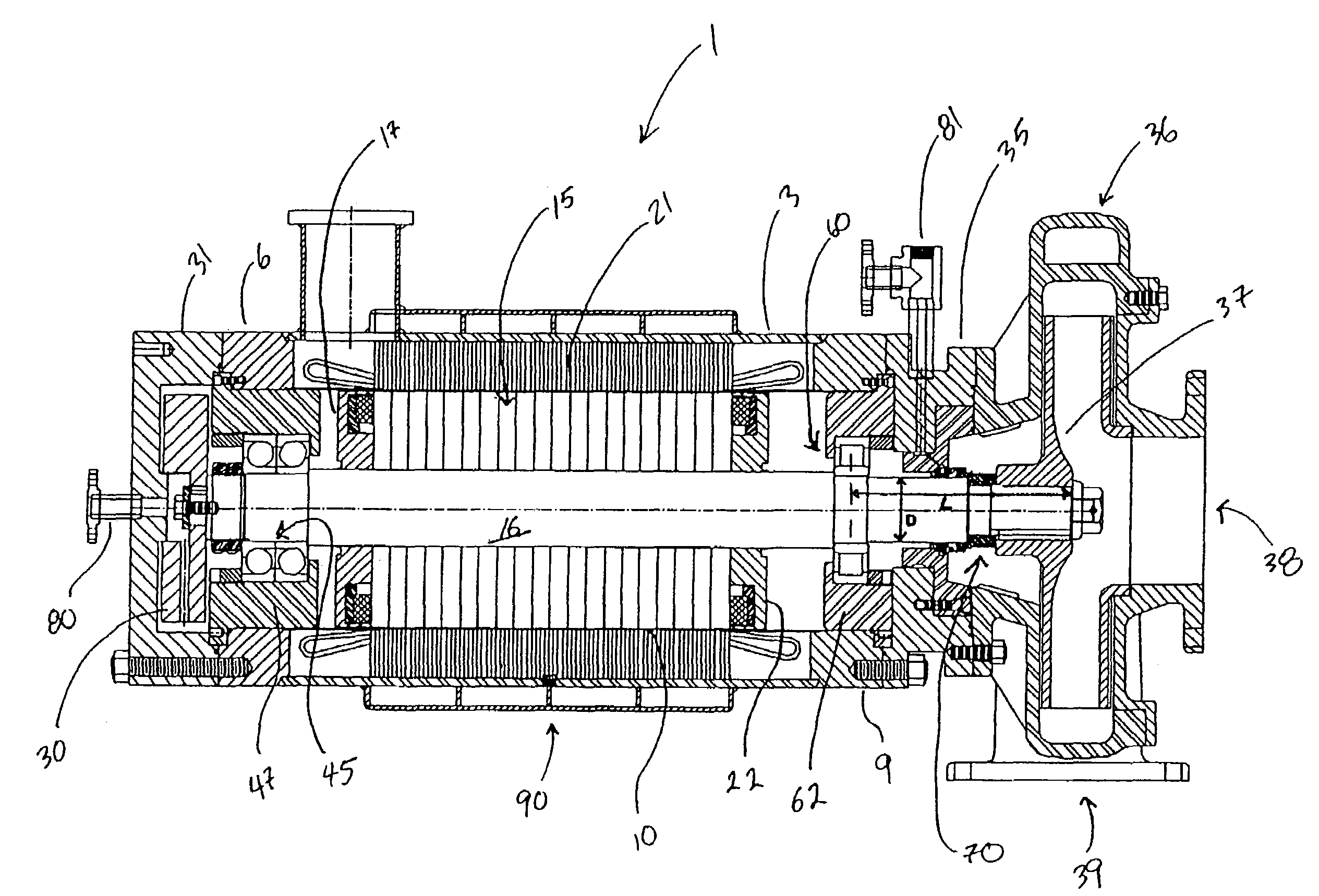
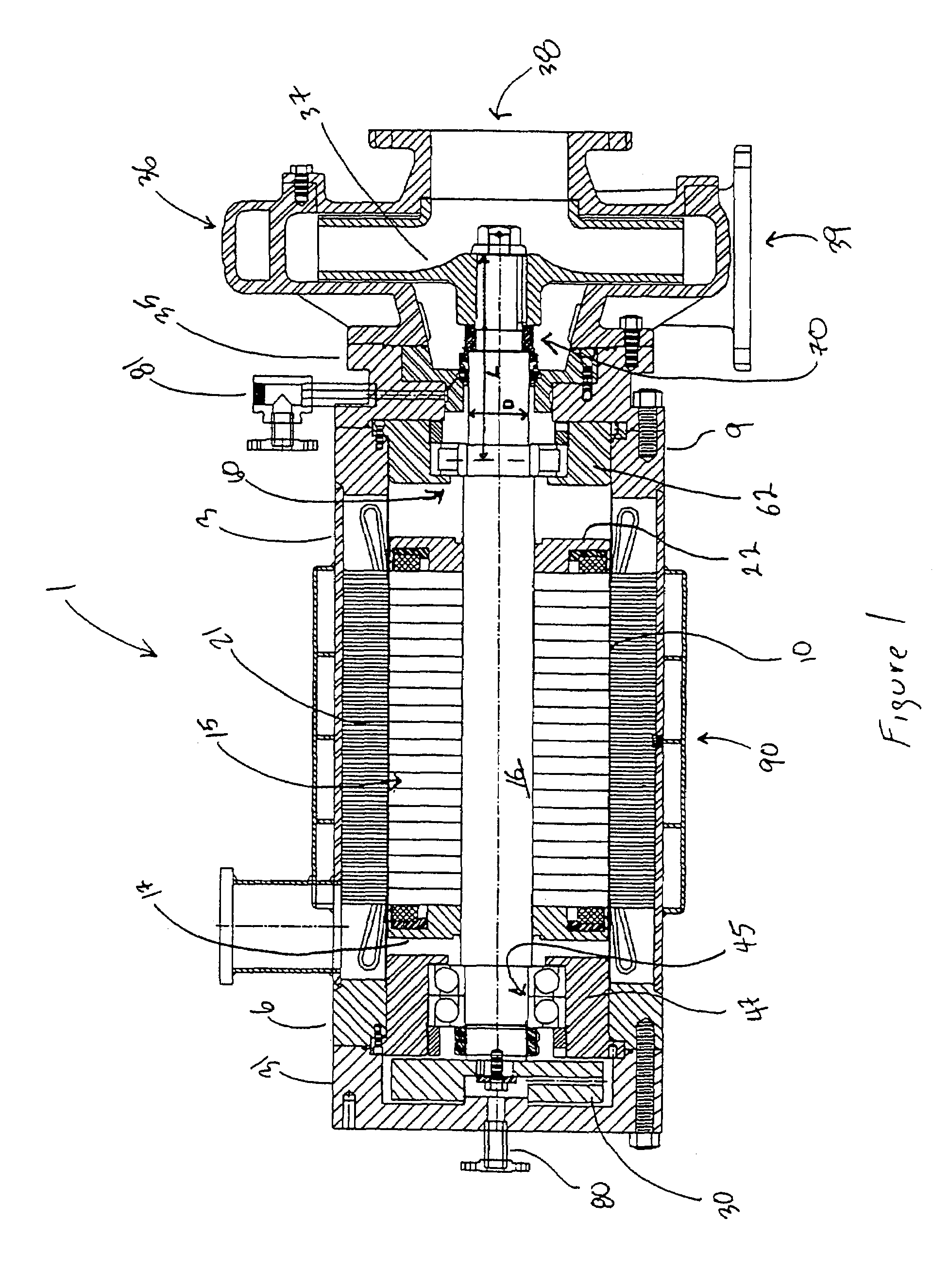
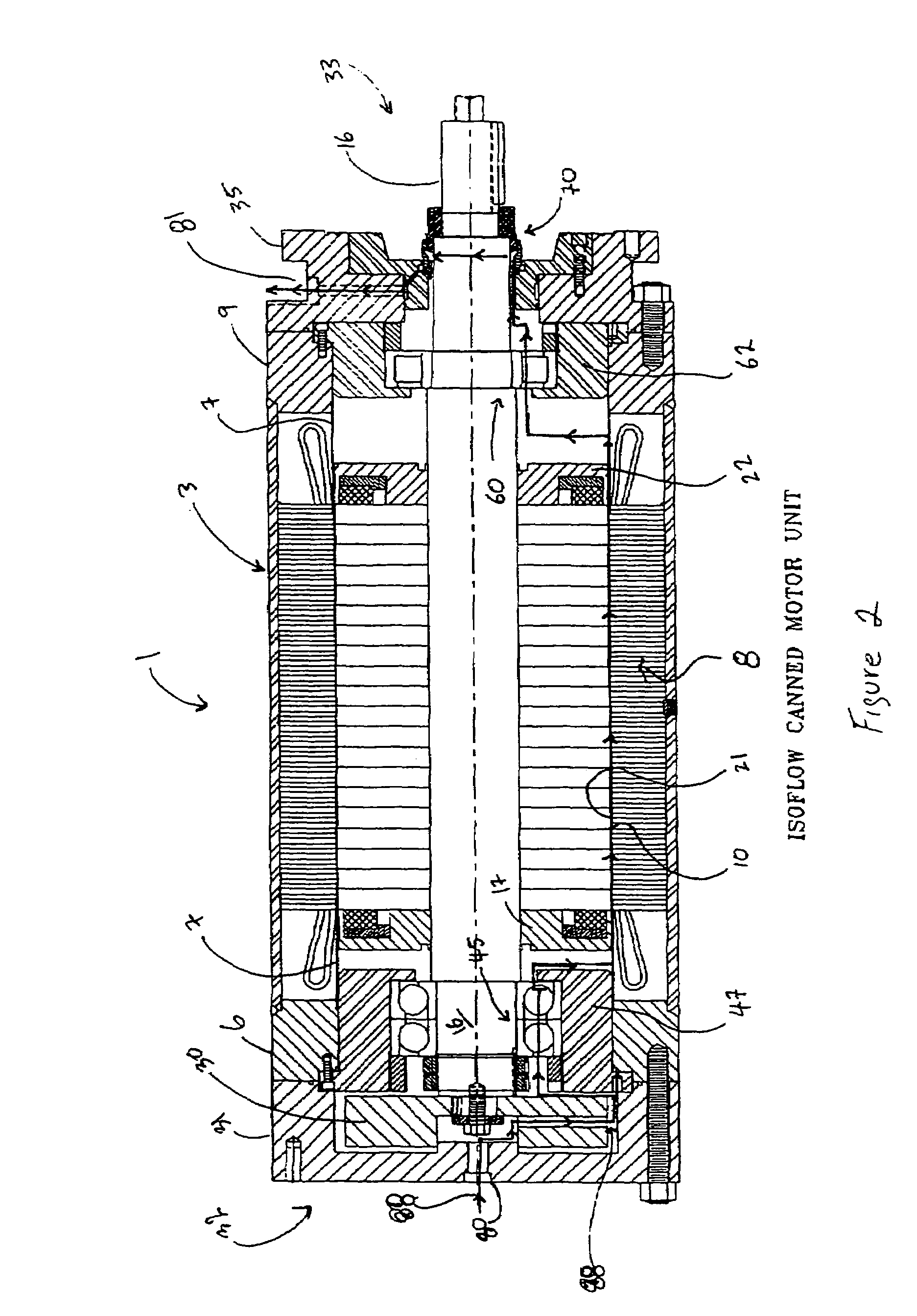
[0025]FIG. 1 is an assembled cross-sectional view of the canned motor 1 of the present invention as it is employed with a standard pump. Thus, in addition to canned motor 1, FIG. 1 illustrates a pump housing 36 with an inlet 38, outlet 39, and pump impeller 37. FIG. 2 illustrates canned motor 1 with pump housing 36 and impeller 37 removed while FIG. 3 shows an exploded view of canned motor 1. Canned motor 1 includes a housing 3 with the motor having an inboard end 33 and an outboard end 32. Beginning at inboard end 33, the main components of motor 1 include mechanical seal 70 through which the end of rotor shaft 16 extends. Mechanical seal 70 engages adapter plate 35 whose outer face is designed to mate with the particular pump housing to be connected to canned motor 1. Positioned behind adapter plate 35 is inboa...


PUM


Abstract

A canned motor has an L3 / D4 ratio of less than 50, with one bearing on one end of the rotor assembly configured to resist longitudinal displacement of the rotor as by an axial shaft load, and another bearing on the other end of the rotor assembly configured to allow limited longitudinal displacement of the rotor assembly within the bearing as from thermal expansion, lengthwise adjustment or pressure from an axial shaft load. The rotor assembly may include a center shaft coaxially extended through a hollow shaft, with rotor windings mounted on the hollow shaft, with the first bearing positioned on one end of the hollow shaft and the second bearing mounted on the second hollow shaft end. A cap and nut assembly on the second hollow shaft end, into which the rotor shaft end is threaded, provides for adjusting the effective rotor shaft length protruding from the motor, and for replacement of the rotor shaft within the hollow shaft without removing the rotor assembly from motor.

Description

RELATED APPLICATIONS[0001]This application is a continuation-in-part of U.S. application Ser. No. 10 / 093,899, filed Mar. 8, 2002, now U.S. Pat. No. 6,759,774, which claims benefit of U.S. Provisional Applications No. 60 / 274,282, filed Mar. 8, 2001. Each of these applications is herein incorporated in its entirety by reference.FIELD OF THE INVENTION[0002]The present invention relates to electric motors which are known in the art as canned or sealless motors as are often used for submerged applications such as to power submergible pumps, and in particular to improvements in such canned motors.BACKGROUND OF THE INVENTION[0003]Canned motors are well known in the art and an example of such motors may be seen in U.S. Pat. No. 4,990,068 which is incorporated herein by reference. The term “canned” is derived from the fact that a first metal cylinder or “can” surrounds the rotor (the “rotor can”) while a second metal cylinder fits between the rotor can and the stator (the “stator can”). A sm...

Claims


Application Information

Patent Timeline
Patent Type & Authority Patents(United States)
IPC IPC(8): H02K5/10H02K5/124H02K5/128H02K5/173H02K7/14
CPCH02K5/124H02K5/128H02K5/1732H02K7/14
Inventor GRIGGS, PAUL EANDREWS, DALE B
Owner FLOWSERVE MANAGEMENT CO
Why Eureka
Try Eureka