
Method and system for combining multiple exposure images having scene and camera motion

a technology of scene and camera motion, applied in the field of digital image data processing, can solve the problems of scene motion and parallax, and the inability to register sub-pixels, and achieve the effect of reducing data costs and seam costs

Active Publication Date: 2007-07-03
MICROSOFT TECH LICENSING LLC
View PDF4 Cites 133 Cited by
  • Summary
  • Abstract
  • Description
  • Claims
  • Application Information

AI Technical Summary

Benefits of technology

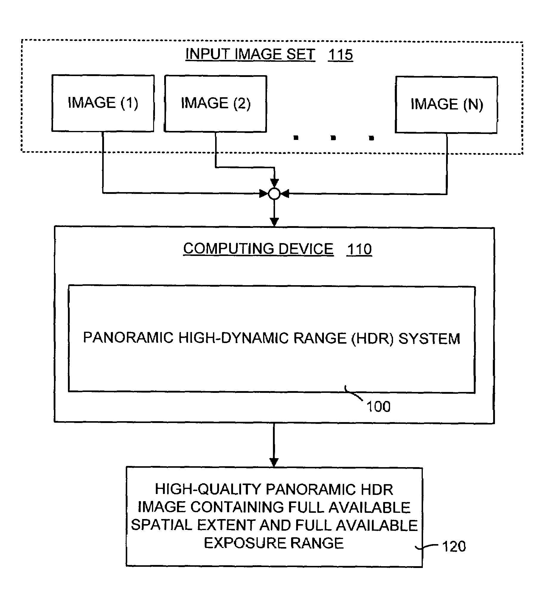
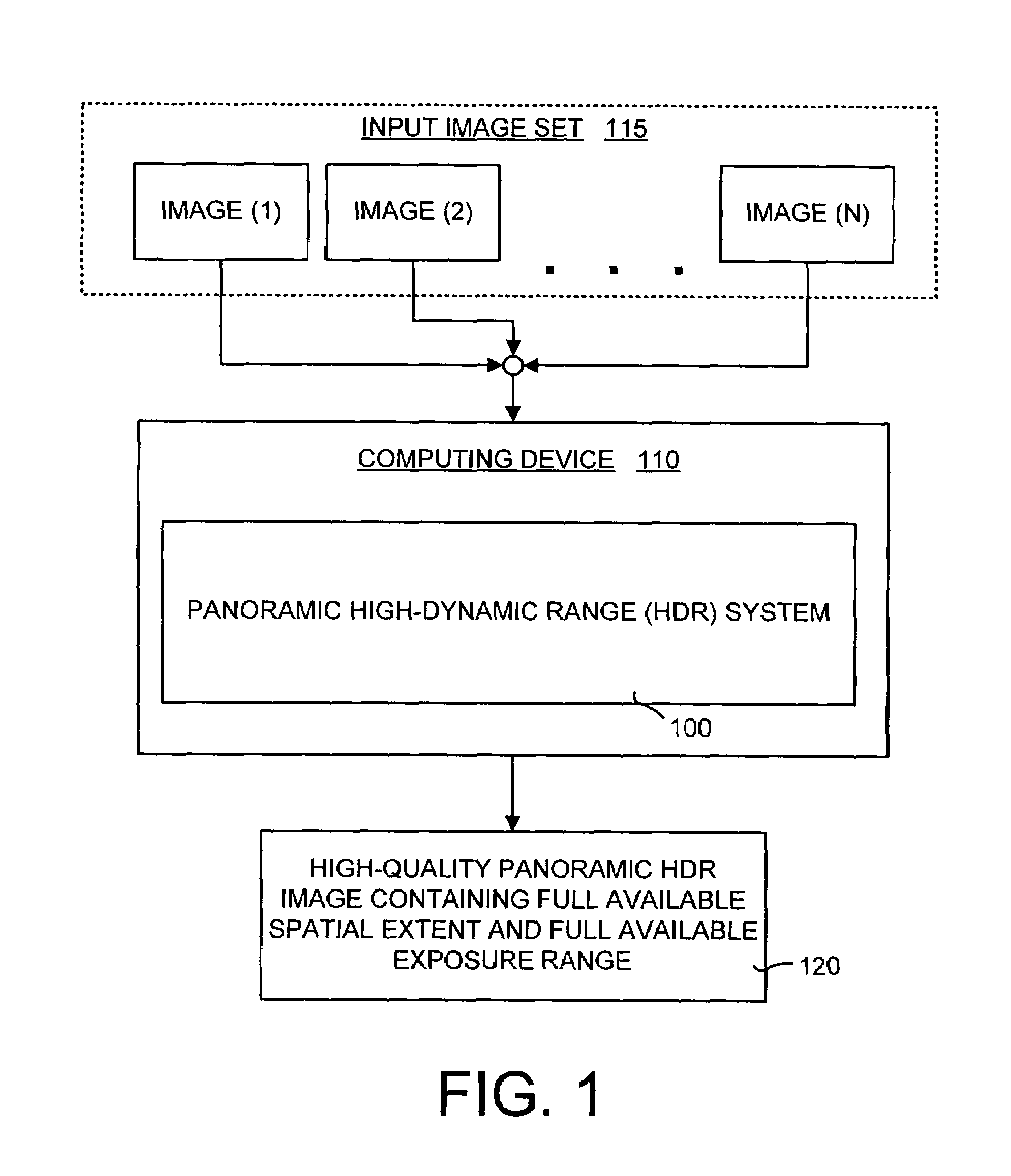
[0012]The second step of the image selection process is a pixel labeling process. In this second step, the complete available dynamic exposure range as captured by the input image set is used to fill in the reference panorama. Base radiance values in the reference image are replaced wherever an overlapping image's radiance value is consistent and produces a higher quality final composite image. The criteria for what is a “better” pixel is defined by introducing data costs and seam costs. The data costs encourage and reward consistency and higher signal-to-noise ratios (SNR) and the seam costs encourage and reward transitions in regions of strong agreement between images of their radiance values. The seam costs are a way to normalize a seam based on the exposure. A graph-cut optimization technique is used to select pixels for inclusion in the final composite image that minimize the data and seam costs. The final composite image is a high-quality panoramic HDR image that contains the spatial extent and the exposure extent of the input image set.

Problems solved by technology

Because of the angular and dynamic limitations of cameras, the generation of a high-dynamic range panoramic images requires several inputs of varying exposures and spatial orientations.
In practice, these inputs are often of a non-static scene, captured with a handheld camera, which often results in scene motion and parallax.
These factors, in addition to imperfect camera calibration, make sub-pixel registration nearly impossible.

Method used


Image

  • Method and system for combining multiple exposure images having scene and camera motion
  • Method and system for combining multiple exposure images having scene and camera motion
  • Method and system for combining multiple exposure images having scene and camera motion

Examples


working example

VII. Working Example

[0090]In order to more fully understand the panoramic high-dynamic range (HDR) system 100 and method disclosed herein, the operational details of an exemplary working example are presented. It should be noted that this working example is only one way in which the panoramic HDR system and method may be implemented.

[0091]In this working example, the panoramic HDR system and method took as input multiple images that captured a scene at varying orientations and exposures. A feature-based registration technique then was used to automatically align the input images. This registration technique is tolerant to exposure differences. Once the input images were geometrically-aligned, they were mapped to the same global radiance space. This mapping was achieved by using a pre-calibrated camera where the camera settings were extracted from exchangeable image file (EXIF) tags. Next, the unknown color gain for each color channel was determined. Once the radiance values for each...


PUM


Abstract

A panoramic high-dynamic range (HDR) image method and system of combining multiple images having different exposures and at least partial spatial overlap wherein each of the images may have scene motion, camera motion, or both. The major part of the panoramic HDR image method and system is a two-pass optimization-based approach that first defines the position of the objects in a scene and then fills in the dynamic range when possible and consistent. Data costs are created to encourage radiance values that are both consistent with object placement (defined by the first pass) and of a higher signal-to-noise ratio. Seam costs are used to ensure that transitions occur in regions of consistent radiances. The result is a high-quality panoramic HDR image having the full available spatial extent of the scene along with the full available exposure range.

Description

TECHNICAL FIELD[0001]The present invention relates in general to the processing of digital image data and more particularly to panoramic high dynamic range (HDR) method and system of combining multiple images having different exposures wherein each of the images may have scene motion, camera motion, or both.BACKGROUND OF THE INVENTION[0002]Many current digital cameras generally are incapable of capturing all spatial directions and all intensities of a given scene. These digital cameras cannot capture a scene such that the image reflects the full dynamic and angular extent that the photographer intended. All digital cameras have a limited field-of-view such that all directions of the scene cannot be captured. This requires a photographer to either pan around the scene taking overlapping images to capture the entire scene or select which sub-part of the scene to capture. In addition, the digital cameras cannot simultaneously capture all intensities of a scene due to the fact that the ...

Claims


Application Information

Patent Timeline
Patent Type & Authority Patents(United States)
IPC IPC(8): G03B7/00G03B41/00G06K9/32
CPCG06T3/4038G06T5/009G06T5/50G06T2207/20208
Inventor UYTTENDAELE, MATTHEW T.SZELISKI, RICHARD S.EDEN, ASHLEY MICHELLE
Owner MICROSOFT TECH LICENSING LLC
Learn More