
Method and apparatus for automatic implantable medical lead recognition and configuration

Inactive Publication Date: 2007-07-03
MEDTRONIC INC
View PDF49 Cites 122 Cited by
  • Summary
  • Abstract
  • Description
  • Claims
  • Application Information

AI Technical Summary

Benefits of technology

[0018]It is a principal object of the present invention to provide an improved interface between conventional lead systems and IMDs.

Problems solved by technology

As leads become smaller, it becomes increasingly difficult to mark leads with the appropriate identification, including manufacturer identification and / or lead model and serial numbers.
This may make it more difficult for a physician to determine which lead is to be inserted into a given port of an implantable medical device (IMD) during an implant procedure.
Although the control unit may use a signal from an electrode to configure the switch, premature sensed events, artifacts and / or EMI may cause the control unit to incorrectly configure the system.
While the above publications teach various improvements to the art, they do not address the problem of identifying and configuring multiple leads and / or other implantable devices for use with an IMD.

Method used


Image

  • Method and apparatus for automatic implantable medical lead recognition and configuration
  • Method and apparatus for automatic implantable medical lead recognition and configuration
  • Method and apparatus for automatic implantable medical lead recognition and configuration

Examples


Embodiment Construction

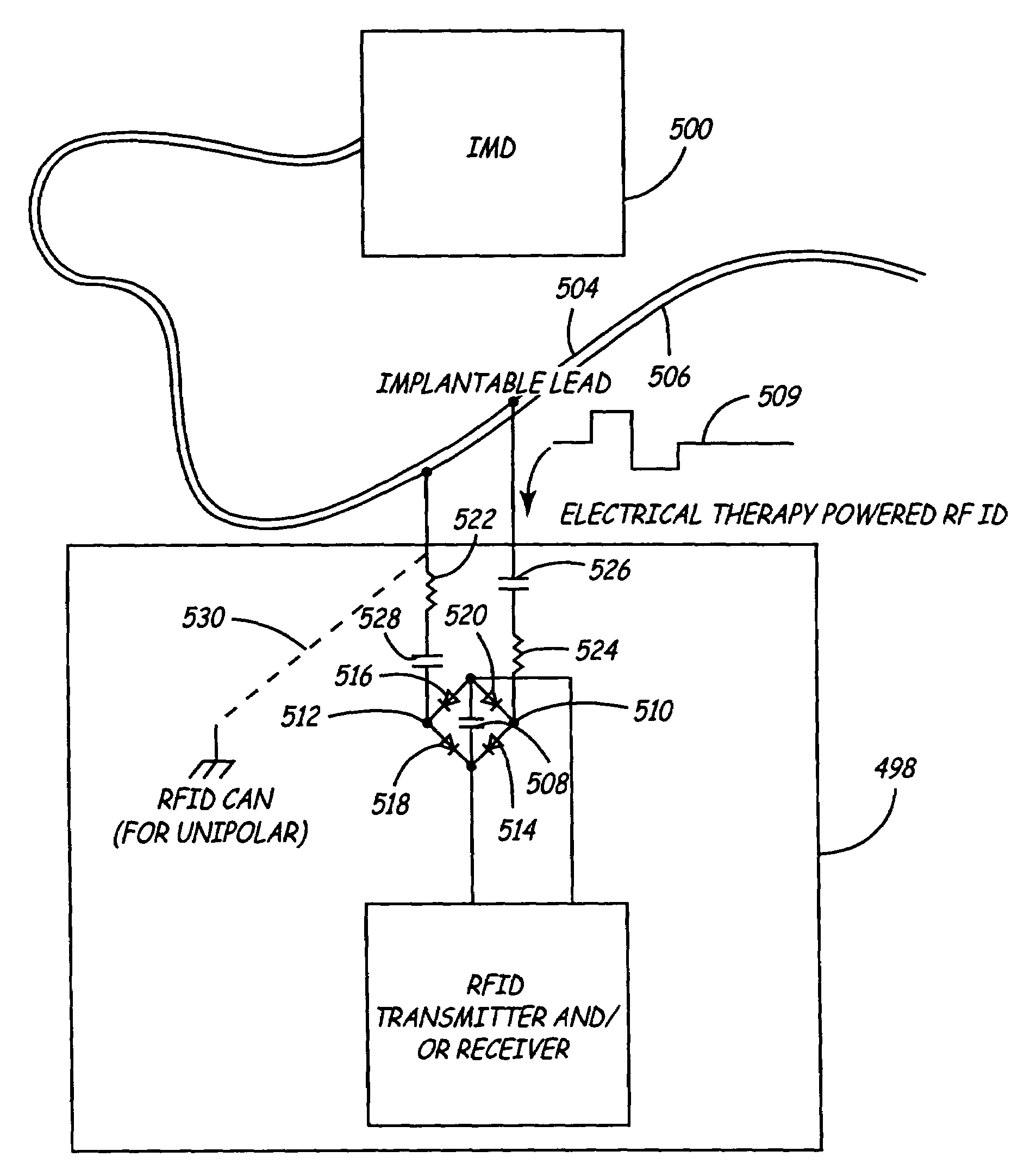
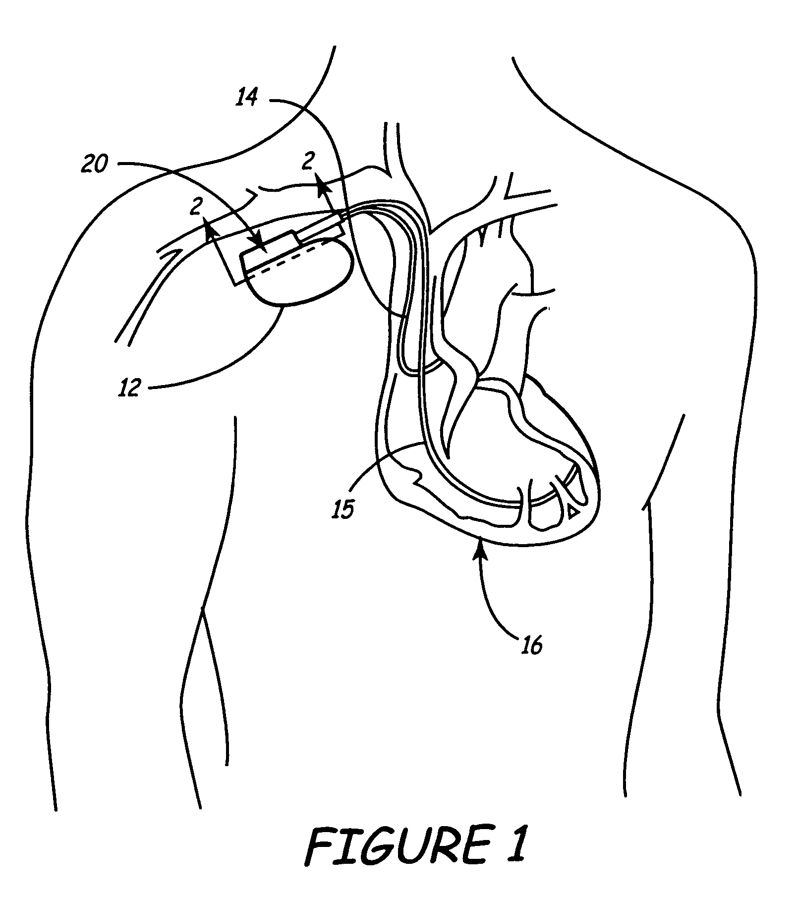
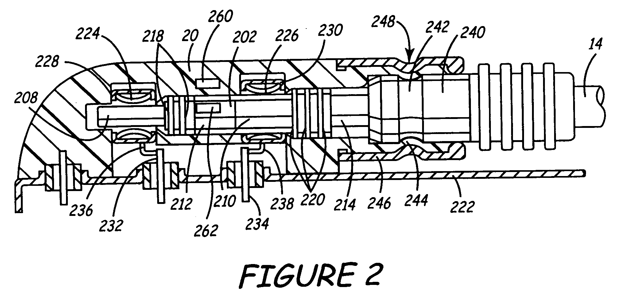
[0037]FIG. 1 is a schematic view of an implantable medical device (IMD) 12 implanted within a body. Leads 14 and 15 are shown coupled to the connector assembly 20 of IMD 12 using one or more feedthroughs. IMD 12, which may be implanted near a human heart 16 or at another location in the body, may be a pacemaker, cardioverter / defibrillator, drug delivery device, brain stimulator, gastric stimulator, nerve stimulator, or any other implantable device. For example, implantable medical device 12 may be an implantable cardiac pacemaker such as that described in U.S. Pat. No. 5,158,078 to Bennett et al., U.S. Pat. No. 5,312,453 to Shelton et al., or U.S. Pat. No. 5,144,949 to Olson et al. Alternatively, IMD 12 may be a pacemaker-cardioverter-defibrillator (PCD) such as those described in U.S. Pat. No. 5,545,186 to Olson et al., U.S. Pat. No. 5,354,316 to Keimel, U.S. Pat. No. 5,314,430 to Bardy, U.S. Pat. No. 5,131,388 to Pless, or U.S. Pat. No. 4,821,723 to Baker, et al. As yet another ex...


PUM


Abstract

An automated identification and configuration system for use with an implantable medical device (IMD) is disclosed. The system includes a first communication circuit that is attached to, or otherwise carried by, a detachable component associated with the IMD such as a medical lead. The communication circuit stores data such as model numbers, serial numbers, technical data, and / or calibration information that describes the additional component. This information may be transferred by the first communications circuit to a second communications circuit that is external to the additional component. This transferred data can be used to automatically configure the internal circuitry and connection functions of the IMD to properly interface with, and support, the additional component. For example, the data can be used to automatically adjust amplifier gains or other sensor circuitry, or to configure a connector block to properly couple to the component. The data may further be entered into a patient record on an external programmer, or may be transferred to a central storage location to be generally accessible to health care providers. In one embodiment, the first communication circuit is a passive RF transponder. This first communication circuit may include a receiver as well as a transmitter to allow the circuit to programmably receive data at the time of component manufacture.

Description

[0001]This application is a divisional of application Ser. No. 09 / 907,308, filed Jul. 17, 2001 now U.S. Pat. No. 6,675,049.BACKGROUND OF THE INVENTION[0002]1. Field of the Invention[0003]The present invention relates generally to implantable medical devices; and, more particularly, to a method and apparatus to automatically identify multiple leads and their proper connection to an implantable medical device such as a pacemaker or cardioverter / defibrillator.[0004]2. Background Art[0005]An implantable intravascular lead assembly is often implanted within a patient's body to provide electrical stimulation to the heart. Such lead assemblies may include one or more electrical conductors that are adapted to be suitably connected to a source of electrical energy, which may be a pacemaker or cardioverter / defibrillator. The electrical conductor, in turn, includes an electrode tip that engages the endocardial or epicardial tissue of the heart to provide stimulation and sensing capabilities. T...

Claims


Application Information

Patent Timeline
IPC IPC(8): A61N1/362A61N1/37A61B5/00A61N1/05A61N1/372A61N1/375A61N1/39
CPCA61N1/37252A61B5/0031A61B2560/0219A61N1/37223A61N1/3752A61N2001/0585A61N1/025A61N1/05A61N1/37254
Inventor THOMPSON, DAVID L.GOEDEKE, STEVEN D.HAUBRICH, GREGORY J.COBIAN, RYANBONDE, ERICSOMMER, JOHN L.WERDER, JONATHANNERISON, NELSBLAHA, ERIC V.
Owner MEDTRONIC INC
Learn More