
Tire pressure estimation

a tire pressure and tire technology, applied in the direction of tyre parts, braking systems, tyre measurements, etc., can solve the problems of affecting the wheel radius, requiring comparatively expensive equipment integrated with the tire, and involuntary stopping in connection with a change of wheels,

Inactive Publication Date: 2007-07-10
NIRA DYNAMICS AB
View PDF6 Cites 30 Cited by
  • Summary
  • Abstract
  • Description
  • Claims
  • Application Information

AI Technical Summary

Benefits of technology

[0016]to provide a robustness with regard to for example various driving styles, cornering, low friction driving cases and split μ situations;
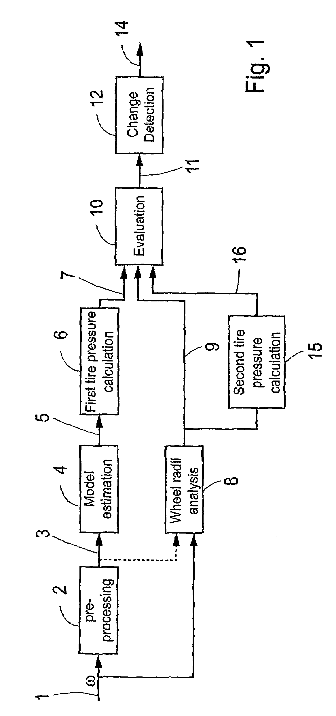
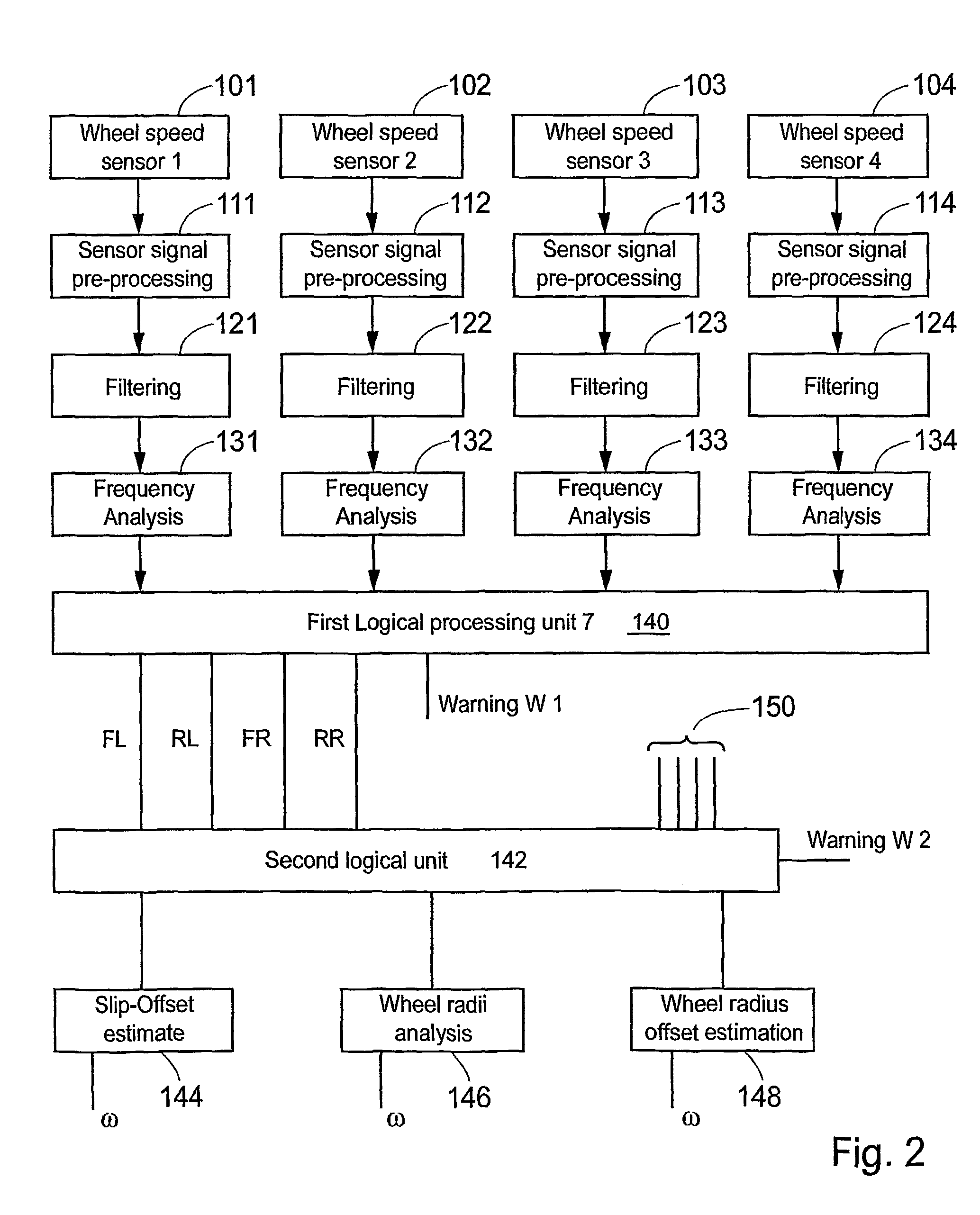
[0023]A specific embodiment of the invention applies a combination of first estimation model in the shape of an improved frequency analysis and a second estimation model in the shape of an improved wheel radii analysis based on measured wheel speed signals. According to an advantageous aspect of the invention, the frequency analysis comprises a second-order discrete time model provided with a Kalman filter for spring parameter estimation, a feature that efficiently attenuates noise and increases the theoretical as well as the practical accuracy of the analysis. More specifically, this embodiment comprises a calculation of the friction parameter slip offset constituting a tire pressure indication value. The slip offset parameter is independent of friction and traction force, and therefore the invention provides a tire pressure estimation that is insensitive to different friction levels and is robust to different driving styles. An embodiment of the wheel radii analysis comprises a computation of:
[0028]An advantage with the present invention is that the functionality works well in vehicles having any number of wheels, even in one-wheeled vehicles and perhaps more practically in two-wheeled vehicles such as motorcycles, in standard four-wheeled cars or lorries with extra wheel pairs.

Problems solved by technology

One such aspect of great importance is related to the tire pressure in the wheels due to the fact that a sudden flat tire can easily cause an accident.
In addition, in areas with a great risk of being robbed at the road an involuntary stop in connection with a change of wheels entails an increased personal risk for the drivers and the passengers.
Direct measurement of tire pressure exists in prior art but requires a comparatively expensive equipment integrated with the tire.
However, the wheel radius is also affected by wear and tear and depends on cruising states, such as cornering and braking.
Wheel radii analysis generally works well in good conditions but is less accurate in case of slippage of the wheels.
An estimate value of each individual tire pressure itself is not possible to obtain through this prior art technology since only the difference between the wheel radii of different wheels are investigated.
Disadvantages with methods based on wheel radii analysis are for example a lack of robustness with regard to different driving styles and loss of functionality during low friction or in split μ situations, i.e. when there is different friction for different tires.
A further disadvantage is that the whole algorithm fails in case of malfunction in one of the wheel speed sensors.
Moreover, simultaneous pressure falls in the tires may in certain cases remain undetected due to the comparative nature of the wheel radii analysis methods.
This method decreases the computational complexity in comparison with the method using the Fast Fourier Transform, since less arithmetical processing is required.
This system is confined to producing a tire pressure signal within the accuracy limits of the wheel speed sensors.
Disadvantages found in prior art tire pressure estimation methods based on frequency analysis is a relatively weak correlation to pressure and a sensitivity to various sources of vibration e.g. dependent on the vehicle velocity.
However, the compensating properties seem to be limited.
Prior art methods all seem to be insufficient in handling high velocities, i.e. situations when the traction torque is large.

Method used


Image

  • Tire pressure estimation
  • Tire pressure estimation
  • Tire pressure estimation

Examples


Embodiment Construction

General Setting

[0062]The invention comprises a method and a realisation of the method that may be realised in hardware, software or a combination thereof. The most feasible realisation of the invention is likely to be in the shape of a computer program product preferably comprising a data carrier provided with program code or other means devised to control or direct a data processing apparatus to perform the method steps and functions in accordance with the description. A data processing apparatus running the inventive method typically includes a central processing unit, data storage means and an I / O-interface for signals or parameter values. The invention may also be realised as specifically designed hardware and software in an apparatus or a system comprising mechanisms and functional stages or other means carrying out the method steps and functions in accordance with the description. In practice, the invention will typically be implemented in a digital or analogue sensor control ...


PUM

PropertyMeasurementUnit
frequencyaaaaaaaaaa
velocityaaaaaaaaaa
frequency analysisaaaaaaaaaa

Abstract

A method, computer program product and apparatus for estimating the pneumatic pressure of a tire on a vehicle, comprising the steps of: receiving as an input a vehicle status sensor signal; estimating first parameter values of an adaptive filter based on a predetermined model on the vehicle status dependent on the vehicle status sensor signal; calculating, dependent on said first model parameter values, a first tire pressure indication value (δ) being dependent on and indicative of the pneumatic pressure of the tire. Specifically, the vehicle status signal may be an input a wheel angular velocity signal (1) and a lateral movement indication signal; the adaptive filter is based on a predetermined model on lateral vehicle dynamics dependent on the angular velocity of said wheel and the lateral movement of said vehicle.

Description

FIELD OF THE INVENTION[0001]The present invention relates generally to a system for tire pressure estimation in a vehicle carried on tire fitted wheels, and more specifically to the detection and estimation of physical parameters dependent on the tire pressure.BACKGROUND[0002]In the design of cars and other vehicles a great deal of attention is today directed to safety aspects. One such aspect of great importance is related to the tire pressure in the wheels due to the fact that a sudden flat tire can easily cause an accident. In addition, in areas with a great risk of being robbed at the road an involuntary stop in connection with a change of wheels entails an increased personal risk for the drivers and the passengers. Another aspect more related to driving economy is based on the fact that a tire having a low air pressure is worn out faster than a correctly filled tire. An indication of the tire air pressure is therefore a means for avoiding unnecessary costs.THE STATE OF THE ART[...

Claims


Application Information

Patent Timeline
Patent Type & Authority Patents(United States)
IPC IPC(8): G01M17/02G01L27/00B60C23/06B60T8/172B60T8/1755
CPCB60C23/061B60C23/062B60T8/1725B60T8/1755B60T2240/03B60T2250/06
Inventor GUSTAFSSON, FREDRIKDREVO, MARCUSPERSSON, NICLAS
Owner NIRA DYNAMICS AB
Learn More