Information-holding unit

Inactive Publication Date: 2007-07-10
DAISHOWA SEIKI CO LTD +1
View PDF26 Cites 13 Cited by
  • Summary
  • Abstract
  • Description
  • Claims
  • Application Information

AI Technical Summary

Benefits of technology

[0017]Concerning the information-holding unit of this invention, the mounting body can be a rotating body and the information carriers can be mounted so that they are symmetrical with respect to the rotation axis

Problems solved by technology

Moreover, even if the type of information-holding unit that saves power in an IC chip by using high-frequency waves to be transmitted as a powe

Method used


Image

  • Information-holding unit
  • Information-holding unit
  • Information-holding unit

Examples


Embodiment Construction

[0026]Preferred embodiments of the information-holding unit according to this invention are hereinafter explained with reference to the attached drawings.

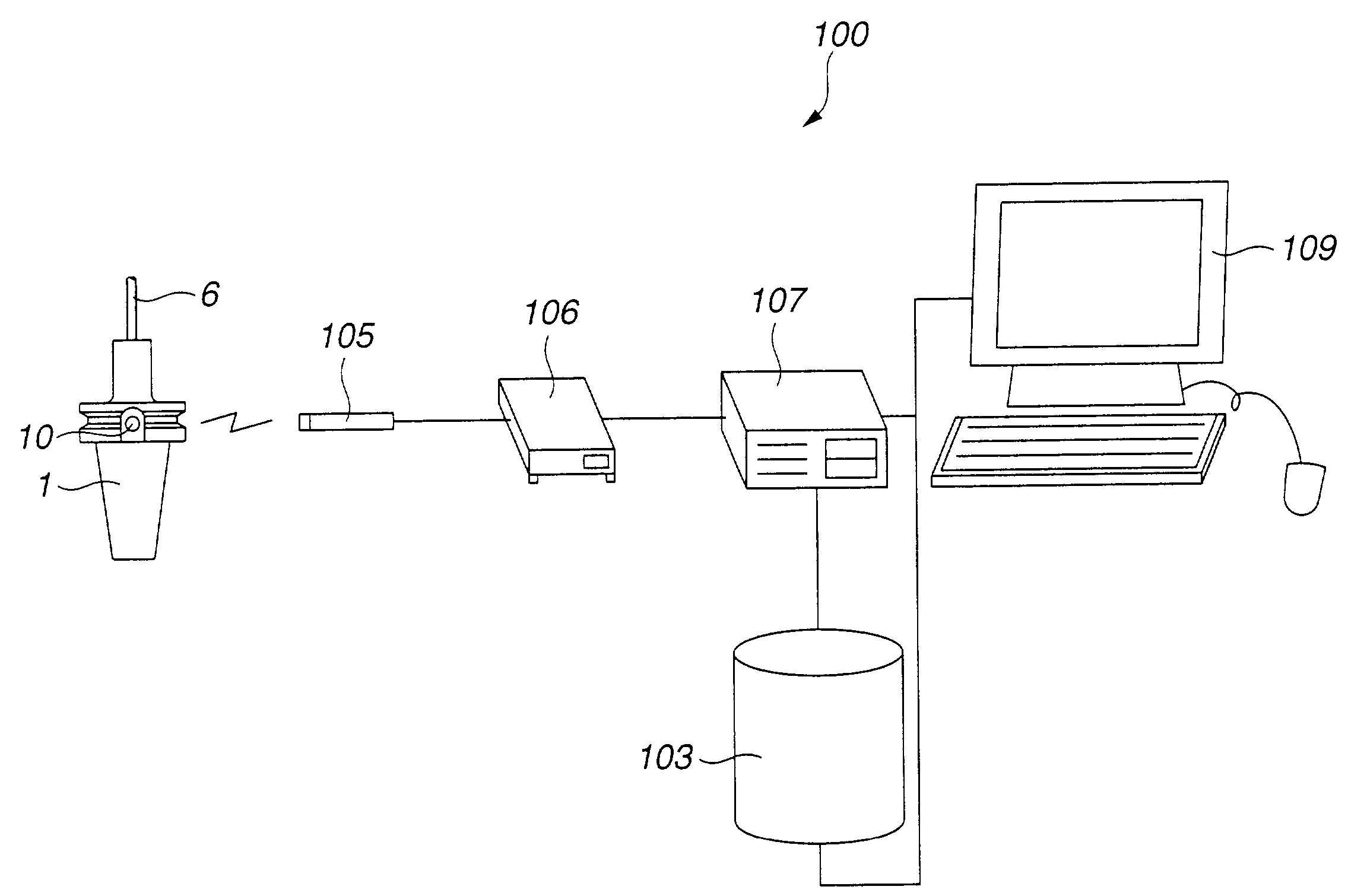
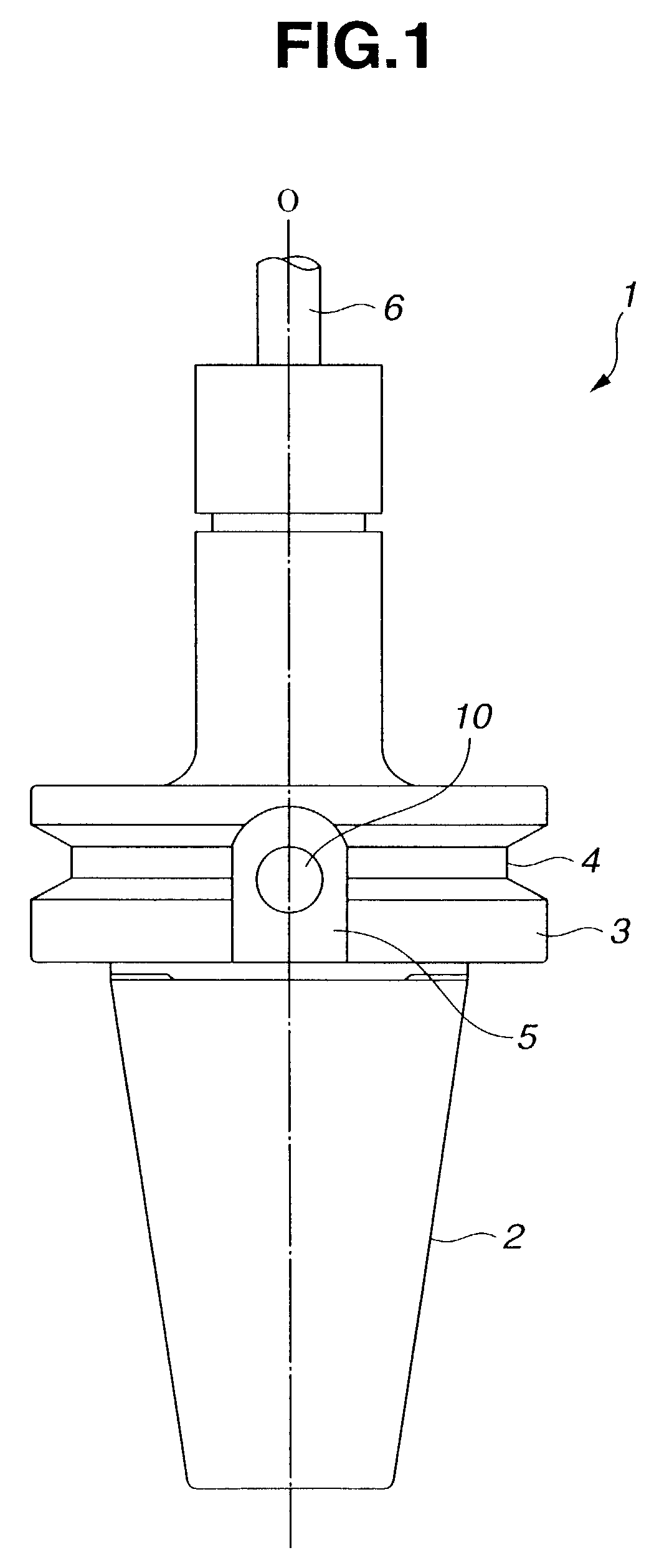
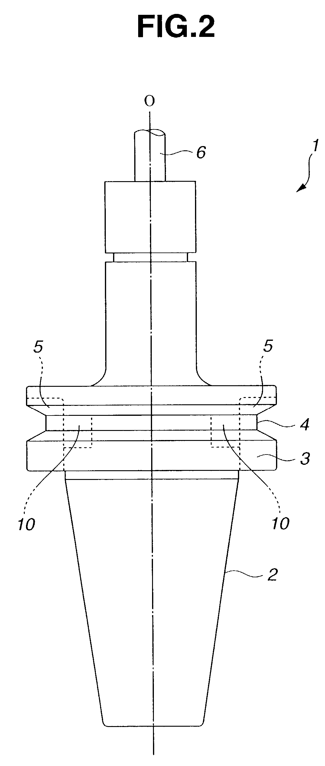
[0027]FIG. 1 is a front view of the information-holding unit according to an embodiment of this invention. FIG. 2 is a side view of the information-holding unit of FIG. 1. FIG. 3 is a diagrammatic illustration of the concept of a system using the information-holding unit of FIG. 1. FIG. 4 is a block diagram of the system using the information-holding unit of FIG. 1.

[0028]A tool 1 as the information-holding unit as shown in FIG. 1 has a reference rotation axis O, and a cutter 6 is mounted at the top end thereof. This tool 1 has a tapered shank 2 which engages with a tapered hole in a main spindle of a machine tool (not shown in FIG. 1). The tool 1 also has a flange 3 which is formed in connection with the tapered shank 2 so as to be opposite the end face of the main spindle. This flange 3 has, on its outer surface, a groove 4 to be ...


PUM


Abstract

An information-holding unit is provided which can minimize increase in cost and which can increase storage capacity as a whole without changing information transferring time. The information-holding unit comprises a plurality of RFID tags with desired specific information stored therein, and a tool holder as a mounting body for mounting these plural RFID tags.

Description

BACKGROUND OF THE INVENTION[0001]1. Field of the Invention[0002]The present invention relates to an information-holding unit on which information carriers with specific information stored therein are mounted.[0003]2. Description of the Related Art[0004]An information-holding unit has been used and made by mounting, on various articles, an information carrier such as a magnetic card, an IC (integrated circuit) card, a bar code, or RFID (Radio Frequency Identification) that stores specific information about such articles. Systems that use such information-holding unit, for example, for identification, collating, management, or conveyance of the above-mentioned articles, are employed in wide-ranging areas such as distribution, FA (Factory Automation), and medical care.[0005]Recently, a non-contact automatic identification system that utilizes RFID techniques capable of reading, without any contact, an IC chip as the information carrier, on which information is written, has been widely ...

Claims


Application Information

Patent Timeline
IPC IPC(8): G06K19/06G06F19/00G06K19/00B23Q11/00B23B27/00B23B31/02B23C5/10B23C9/00B23Q3/155G05B19/12G06K19/04G06K19/07
CPCB23B31/02B23C5/109B23Q3/15546G05B19/128G06K19/04B23B2231/10Y10T483/134G05B2219/33192G05B2219/33203G05B2219/49304G05B2219/50338G05B2219/31095G06K17/00
Inventor KOMINE, TSUYOSHINAKAJIMA, HIDEHITO
Owner DAISHOWA SEIKI CO LTD
Why Eureka
Try Eureka