Vehicle cargo bed extender

a technology for extenders and cargo vehicles, which is applied in the direction of transportation and packaging, transportation items, and transportation vehicles, etc., can solve the problems of affecting the service life of the extender, the inability to withstand bumping, and the undesirable configuration of the storage bed, so as to minimize movement and vibration, and improve the strength and rigidity of the extender

Active Publication Date: 2007-07-10
LUND MOTION PRODS
View PDF66 Cites 46 Cited by
  • Summary
  • Abstract
  • Description
  • Claims
  • Application Information

AI Technical Summary

Benefits of technology

[0012]The extender may also comprise a first L-shaped section defining the first side wall and a first portion of the connecting wall and a second L-shaped section defining the second side wall and a second portion of the connecting wall. Advantageously, these L-shaped portions significantly increase the strength and rigidity of the extender, enhancing its ability to withstand bumping by heavy cargo, such as motorcycles, as well as external impact.
[0013]In one embodiment, there is provided at least one buckle secured to one of the walls sized and shaped to be releasably locked to the latch of the vehicle tailgate. Significantly, the buckle provides a supplemental attachment point which minimizes movement and vibration of the extender while driving and is quickly releasable by using the vehicle tailgate's own opening mechanism.
[0020]According to one embodiment, a method is described for an individual to mount a vehicle bed extender on a vehicle without tools including: aligning a first mount fixed with respect to the extender with a first space defined by the first station and aligning a second mount fixed with respect to the extender with a second space defined by the second station; moving the bed extender such that the first mount moves radially through the first space with respect to an axis defined by the first station and the second station and the second mount moves radially with respect to the axis through the second space; and pivoting the extender about the axis so that the first mount cooperates with the first station and the second mount cooperates with the second station to prevent radial movement of the first mount with respect to the axis and the second mount with respect to the axis.
[0022]In one embodiment, there is provided a truck bed extender for use with a vehicle having an open storage bed having a rear end, a first standing side panel to one side of the bed, a second upstanding side panel to an opposite side of the bed and a tailgate, a first mounting station fixed with respect to the first upstanding panel defining a first station surface and a second mounting station fixed with respect to the second upstanding panel defining a second station surface. The extender includes a first sidewall, a second sidewall, a connecting wall extending between the first sidewall and the second sidewall, a first mount secured to the first sidewall, and a second mount secured to the second sidewall. The first sidewall of the second sidewall and the connecting wall cooperate to form a generally U-shaped frame. The first mount defines a first mount surface and the second mount defines a second mount surface. The first station surface and the first mount surface, and the second station surface and the first mount surface cooperate to secure the apparatus to the vehicle so that the connecting wall is in an upright position over the tailgate rearward of the rear end of the bed. The tailgate defines a latch to secure the tailgate to at least one of the first upstanding panel and the second upstanding panel. The truck bed extender further includes at least one interlock member secured to one of the walls sized and shaped to be releasably captured by the latch of the tailgate. Desirably, the interlock member comprises a buckle or a cylindrical interlock portion rigidly secured to the connecting wall. Significantly, this stabilizes the tailgate against movement when the vehicle strikes an object, such as a speed bump.
[0031]In the mounting station of the foregoing embodiment, the stationary portion can further comprise a stationary cusp, a lower curved portion, and a vertical portion. The stationary cusp, the lower curved portion, and the stop cooperate to define a circle through about 300 degrees when the moveable portion is in the first position. The interlocking portion is substantially circular in shape and has an outer diameter that is just smaller than the inner diameter of the circle defined by the stationary cusp, the lower curved portion, and the stop. A maximum distance between the vertical portion and the stationary cusp is larger than the outer diameter such that when the moveable portion is in the second position the interlocking portion can pass between the stationary cusp and the vertical wall without such passage being impaired by the stop.
[0033]According to one embodiment, a method is described for an individual to mount a vehicle bed extender on a vehicle having an open storage bed having a rear end, a first upstanding side panel to one side of said bed, a second upstanding side panel to an opposite side of said bed and a tailgate, a first mounting station fixed with respect to said first upstanding panel, and a second mounting station fixed with respect to said second upstanding panel. The method comprises: providing a generally U-shaped vehicle bed extender, said vehicle bed extender having a first side wall, a second side wall, a connecting wall extending between said first side wall and said second side wall, a first mount with a first interlocking portion secured to said first side wall, and a second mount with a second interlocking portion secured to said second side wall; moving a moveable portion of said first mounting station and a moveable portion of said second mounting station such that said moveable portions are in a first position that allows said first mounting station to engage one of said first interlocking portion and said second interlocking portion and allows said second mounting station to engage the other of said first interlocking portion and said second interlocking portion; positioning said first side wall and said second side wall between said first side panel and said second side panel, such that said first interlocking portion is positioned above but not engaged by one of said first mounting station and said second mounting station and said second interlocking portion is positioned above but not engaged by the other of said first mounting station and said second mounting station, so that said connecting wall is in substantially vertically aligned over said tailgate rearward of said rear end of said bed and said extender provides access from above to a space between said first side wall and said second side wall; moving said bed extender substantially downward without substantially changing said substantial vertical alignment of said connecting wall, such moving causing said first mounting station of said first side panel to engage one of said first interlocking portion and said second interlocking portion, and causing said second mounting station of said second side panel to engage the other of said first interlocking portion and said second interlocking portion, so that said bed extender is in a first mounting position with said connecting wall in a substantially vertical position over said tailgate rearward of said rear end of said bed and said extender provides access from above to a space between said first side wall and said second side wall; and moving said moveable portion of said first mounting station and said moveable portion of said second mounting station such that said moveable portions are in a second position that prevents disengagement of said first mounting station to one of said first interlocking portion and said second interlocking portion and prevents disengagement of said second mounting station from the other of said first interlocking portion and said second interlocking portion.

Problems solved by technology

Unfortunately, often the storage bed is of an undesirable configuration for the load being transported.
Unfortunately, this raises the risk that the load will fall out of the back of the truck, or that the load will need to be tied down, taking additional time.

Method used


Image

  • Vehicle cargo bed extender
  • Vehicle cargo bed extender
  • Vehicle cargo bed extender

Examples


Embodiment Construction

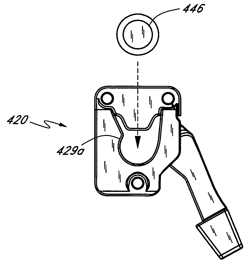
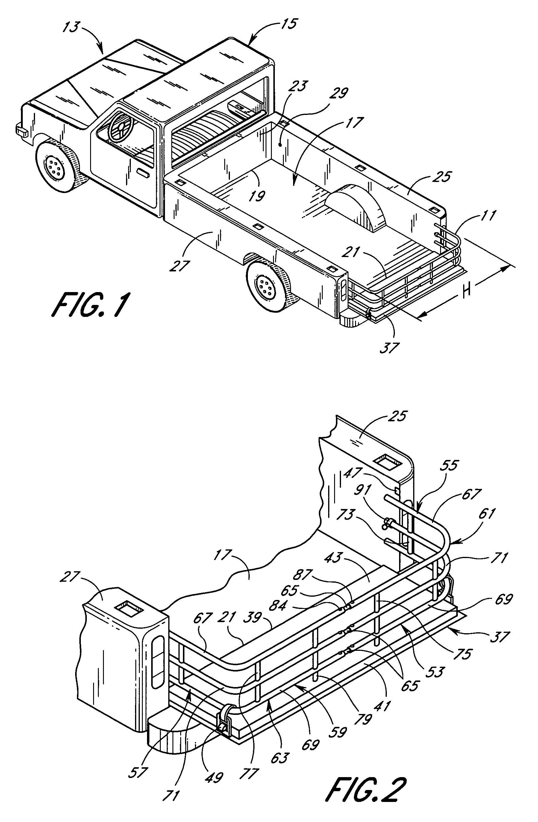
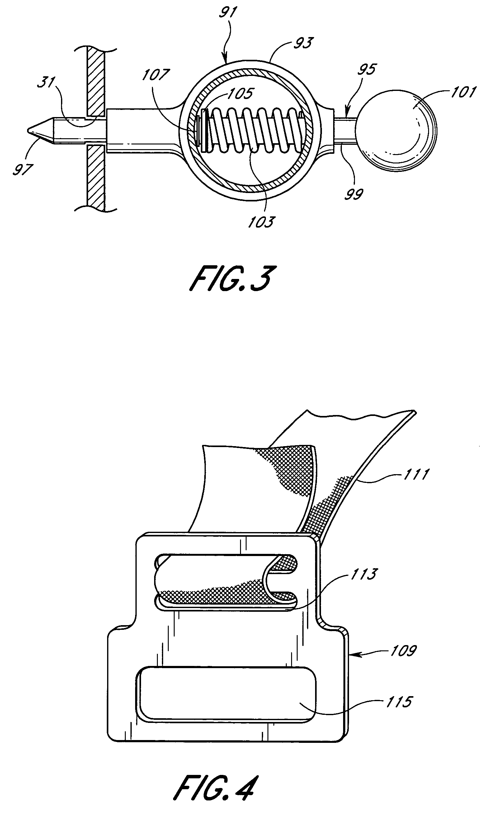
[0075]The preferred embodiment of a multi-purpose apparatus or truck bed extender 11 will now be described with reference to the figures. Referring to FIGS. 1 and 2, the truck bed extender 11 is shown mounted on a truck 13 having a cab 15 to the rear of which is a storage bed 17. The storage bed 17 has a front end 19 and a rear end 21. The front end 19 of the storage bed is defined by a front upstanding panel 23 and the sides of the storage bed are defined by a first side upstanding panel 25 and a second side upstanding panel 27. The first side upstanding panel 25 defines a first forward mounting station or aperture 29 and a first rearward mounting station or aperture 31 (FIG. 3), the purpose and location of which will be discussed in greater detail below. Likewise, the second side upstanding panel 27 defines a second forward aperture (not shown) and a second rearward aperture (not shown).

[0076]At the rear end 21 of the storage bed 17 is a tailgate 37. The tailgate has a hinge end 3...


PUM


Abstract

A vehicle bed extender particularly adapted for ease of installation and removal. The extender includes a first side wall, a second side wall, a connecting wall, a first mount, a second mount, a first mounting station, and a second mounting station. The connecting wall, the first side wall, and the second side wall cooperate to form a generally U-shaped frame. The first mounting station and the second mounting station each comprise a stationary portion and a moveable portion configured such that the moveable portion, in a first position, cooperates with the stationary portion to engage the first mount or the second mount and to prevent disengagement. The moveable portion of the first mounting station and the second mounting station can be moved by a manual application of pressure to a second position which allows such disengagement.

Description

REFERENCE TO RELATED APPLICATIONS[0001]This application claims priority to U.S. Provisional Patent Application No. 60 / 612,544, which was filed Sep. 23, 2004 and is entitled “VEHICLE CARGO BED EXTENDER.” The foregoing provisional patent application is hereby incorporated by reference in its entirety into this application.[0002]This application is also related to but does not claim priority to the following United States Patent Applications: U.S. patent application Ser. No. 10 / 914,384, filed Aug. 9, 2004, which is pending, which is a continuation of U.S. patent application Ser. No. 10 / 171,456, filed Jun. 11, 2002, which issued as U.S. Pat. No. 6,805,392, which is a continuation of prior U.S. patent application Ser. No. 09 / 524,332, filed Mar. 13, 2000, which issued as U.S. Pat. No. 6,402,215, which is a continuation of prior U.S. patent application Ser. No. 09 / 347,472, filed Jul. 2, 1999 and abandoned, which claims the benefit of prior U.S. Provisional Patent Application No. 60 / 091,623...

Claims


Application Information

Patent Timeline
Patent Type & Authority Patents(United States)
IPC IPC(8): B62D33/02
CPCB62D33/0273
Inventor LEITNER, HORST
Owner LUND MOTION PRODS
Why Eureka
Try Eureka