
Technique for power control in optical networks

a technology of optical network and power control, applied in the field of power control in optical network, can solve the problems of incorrect reaction of the system, degradation of the optical performance of the system, and inability to correctly adjust the output power of the amplifier in the link, so as to achieve maximum operation and simple power control

Active Publication Date: 2007-07-10
ECE TELECOM LTD
View PDF10 Cites 6 Cited by
  • Summary
  • Abstract
  • Description
  • Claims
  • Application Information

AI Technical Summary

Benefits of technology

[0023]1. The method allows automatic configuration of the amplifier chain by simply connecting the fiber. Upon performing an initial calibration of the required output power per channel at the first amplifier in the chain all other amplifiers in the chain need only to be connected to the fiber and they will automatically calibrate to the correct gain values. This frees the network installation personnel from the need to calibrate and re-calibrate the network repeatedly going from site to site with all the necessary monitoring equipment until the network is stabilized.
[0036]A further idea of the present invention is to share the responsibility of compensating power loss changes, caused by degradation / improvement of one or more optical spans, between a number of amplifiers in the chain, while ensuring proper reaction of the chain nodes to cases of fiber cut.
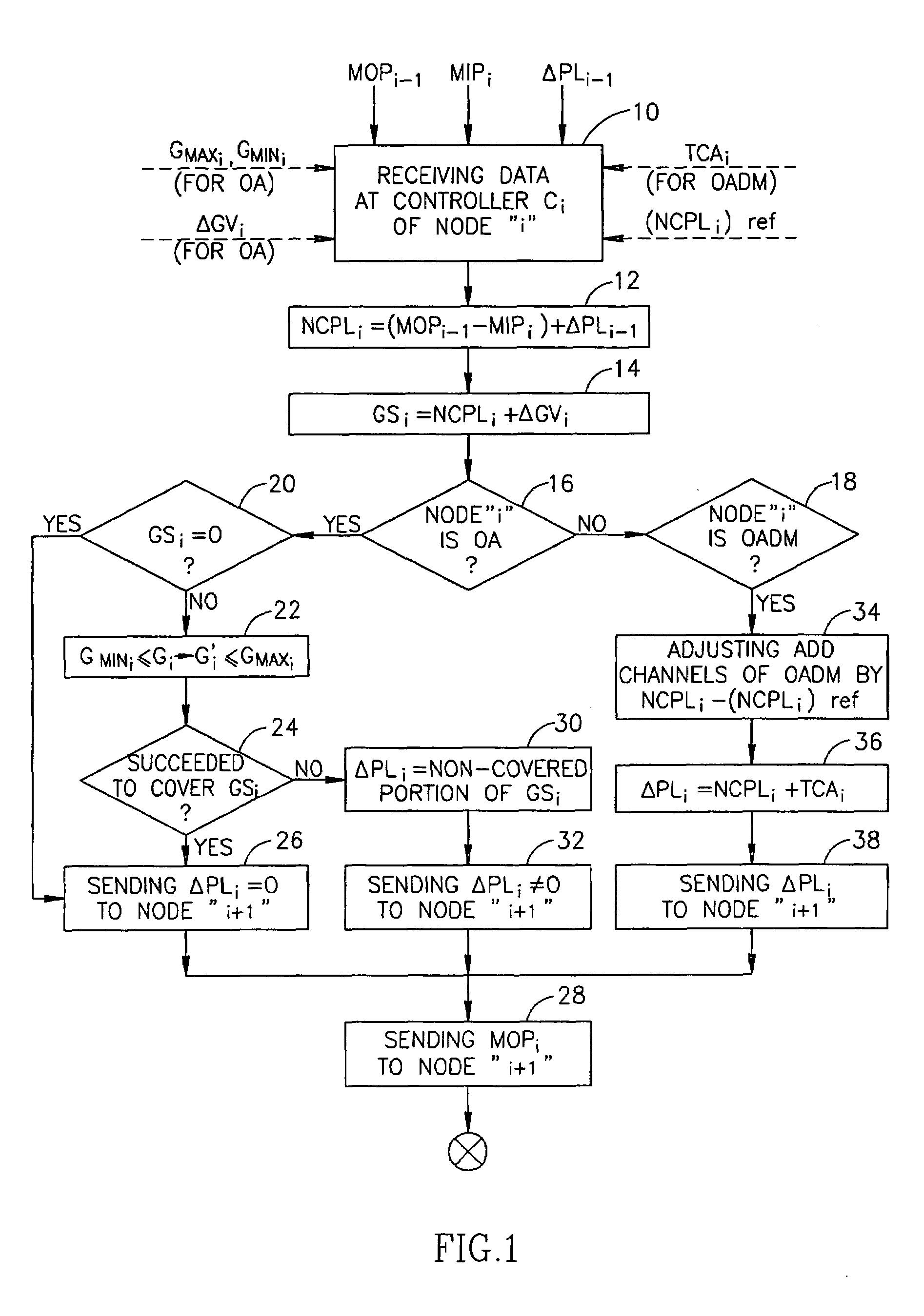
[0037]To implement the above idea, the step of obtaining information may further comprise obtaining a value of accumulated non-compensated power loss at the preceding node (ΔPL), and transmitting said fulfilled information from a preceding node to its following node in the chain (or to a central processor), the method thereby ensuring distributed compensation of power loss changes if occur in one or more spans of the chain.
[0045]The operations of obtaining the information of MOP and of the gain control can be performed on the basis of periodical monitoring and by using pre-selected thresholds, so as to prevent excessive sensitivity of the system. For example, values of MOP can be measured periodically to confirm that there is a valuable MOP, and more often only in cases the MOP changes over a pre-selected threshold; the gain of a node can be left unchanged if the change of the power loss NCPLi between two successive monitoring sessions is no more than ±0.5 dB. Moreover, a so-called hold off time can optionally be selected to delay reaction of the node in order to recheck the changes thereby preventing excessive fluctuations in the chain.
[0046]Owing to the fact that amplifiers of the chain compensate any power loss changes (if occur), the proposed method ensures that any changes in a number of optical channels are automatically reacted to without calculating the number of channels. In other words, upon preliminary calibration of power per channel in the chain, the method enables preserving the calibrated power per channel automatically, also in cases when optical channels are added / dropped so the number of channels in some spans of the chain changes. Reaction of the nodes will actually depend on the input power proportional to the output power of the preceding node and regardless a number of incoming channels, since any changes in the span attenuation, should they distort the correct proportion, would be compensated.
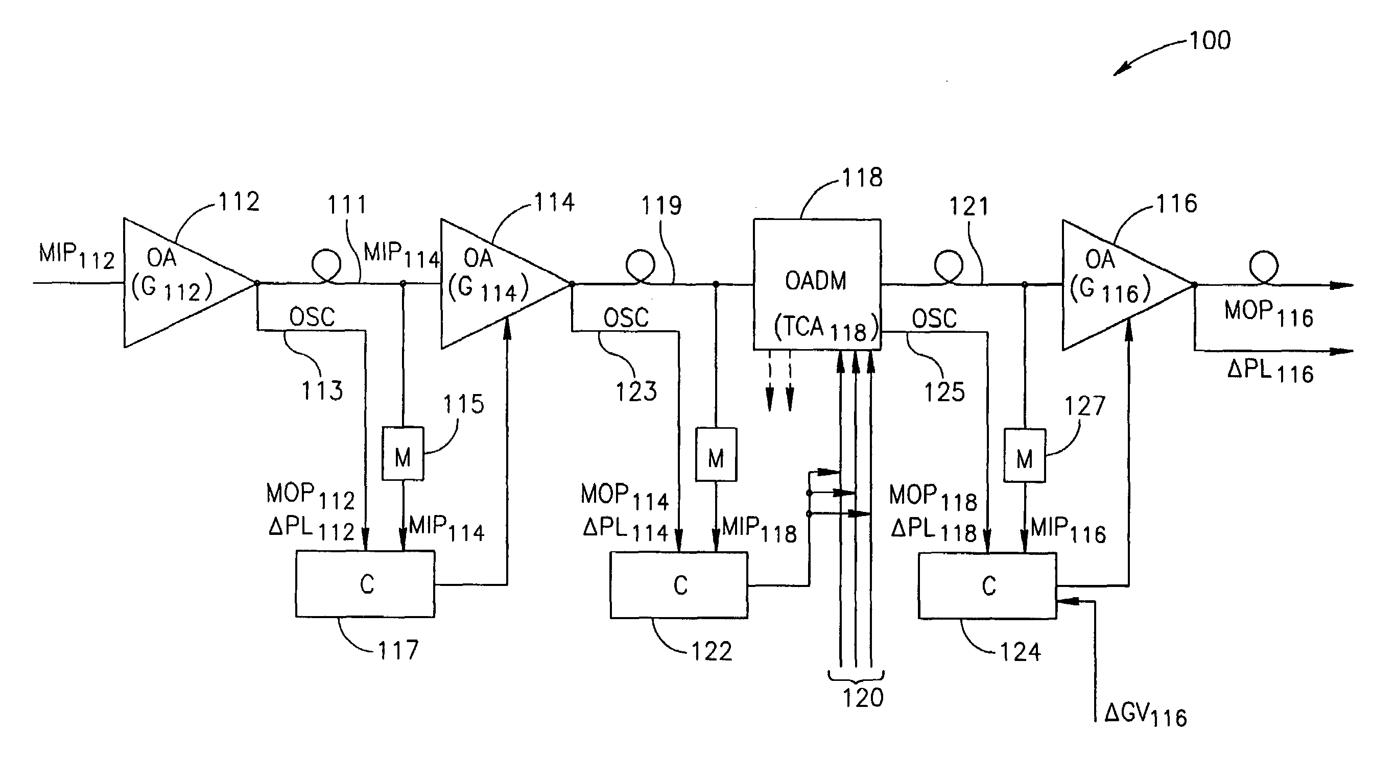
[0075]As has been mentioned, the intermediate node, being an optical amplifier, is operative to compensate the non-compensated power loss by controlling the gain of the node.

Problems solved by technology

There are a number of problems known in the field of optical communications, which concern regulating power of multi-channel optical transmission.
However, such a mechanism reacts incorrectly to events such as a fiber cut in a specific span of a link with OADMs (Optical Add Drop Multiplexers).
Indeed, a fiber cut drastically changes the actual number of channels at more than one successive nodes, so the output power of the amplifiers in the link will not be correctly adjusted.
The erroneous adjustment will most likely cause a degradation in optical performance of the system.
The system counts the channels on the ad-hoc basis but is unable to predict the number of active optical channels in case of a fiber cut, which would be important to prevent ill effects of transient periods in the network until the channel count mechanism is updated.
Neither of the presently known systems allows simply and suitably adapting power control in an optical network to different types of faults, for example reacting adequately to a fiber cut and / or a fiber degradation due to fiber bend or fiber aging.

Method used


Image

  • Technique for power control in optical networks
  • Technique for power control in optical networks
  • Technique for power control in optical networks

Examples


Embodiment Construction

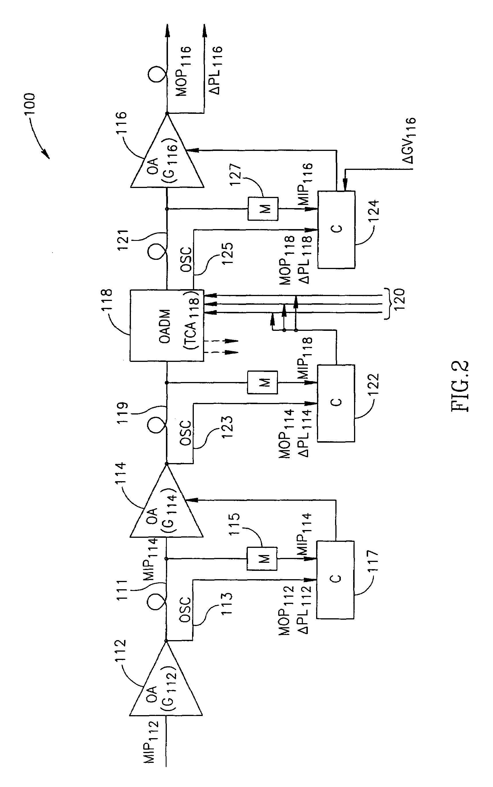
[0081]To explain the invention in more detail, let us consider any two adjacent nodes in the optical chain. Let we have the 1st or preceding node and the 2nd or present node. Each of the nodes is either an optical amplifier or OADM. The 1st node receives an optical signal from a preceding node via a 1st optical span, and is connected to 2nd node via a 2nd optical span. As mentioned, any of the nodes may constitute an amplifier having its gain that can be regulated up to its maximal gain, or an OADM which does not have a gain while has a capability to regulate power of add channels according to power of incoming channels. A real chain may comprise passive elements which just pass there-through both the information channels and the supervisory channel of the optical transmission; such elements will be considered portions of optical fiber spans, and not the nodes. Nodes may either have embedded processors, or use a centralized one.

[0082]The 1st node should be capable to send two kinds ...


PUM


Abstract

A technique for maintaining a required value of power per optical communication channel in a chain of optical nodes (112, 114, 118, 116) connected by optical fiber spans (111, 119, 121), wherein at least some of the nodes include optical amplifiers (112, 114, 116) with controllable gains, the technique comprises performing automatic gain control at the optical amplifiers so that, in the frame of power gain of each particular optical amplifier (114, 116), to compensate a preceding span loss. The span loss is calculated as power loss on an optical fiber span (111,121) incoming the particular amplifier.

Description

FIELD OF THE INVENTION[0001]The present invention relates to a technique for controlling and regulating the power level of optical signals transmitted in an optical telecommunication network both in the regular regime, and in cases of fiber cut and span attenuation changes.BACKGROUND OF THE INVENTION[0002]There are a number of problems known in the field of optical communications, which concern regulating power of multi-channel optical transmission.[0003]In advanced network configurations, sites can possibly contain either optical amplifiers or Optical Add Drop Multiplexers (OADM), or both. An optical trail may start and terminate at any site according to a customer's use. For example, due to the fact that OADM is capable of dropping and adding optical channels, some trails may start or terminate at the add / drop ports of OADM and the number of optical channels in spans before and after OADM may differ significantly. In such configurations, a fiber cut in a span / section beyond the en...

Claims


Application Information

Patent Timeline
IPC IPC(8): H04B10/08H04B10/00H04B10/04H04J14/02H04B10/02H04B10/077H04B10/17H04B10/293
CPCH04B10/0771H04B10/0775H04B10/2935
Inventor MUZICANT, TALHARRIS, DAVID
Owner ECE TELECOM LTD
Learn More