Predictive control system and method

a control system and prediction technology, applied in the direction of position/direction control, ac-dc conversion, analog and hybrid computing, etc., can solve the problems that controllers that are verified using such software cannot be easily modified to take proper account of real life effects, and commercially available simulation software does not take into account all real life effects

Inactive Publication Date: 2007-07-10
ZETACON CORP
View PDF51 Cites 42 Cited by
  • Summary
  • Abstract
  • Description
  • Claims
  • Application Information

AI Technical Summary

Problems solved by technology

However, commercially available simulation software does not take into account all real life effects (e.g. switching delays, and / or interlock delays).
Ignoring these effects can substantially affect simulation results.
Further, controllers that are verified using such software cannot be easily modified to take proper account of real life effects.
For this reason, standardization of power electronic designs has been difficult to achieve.
However, post production revisions to a controller designed using these kinds of pre-design simulation techniques, is generally costly, time consuming and unmanageable, leading to early design obsolescence.

Method used


Image

  • Predictive control system and method
  • Predictive control system and method
  • Predictive control system and method

Examples


Embodiment Construction

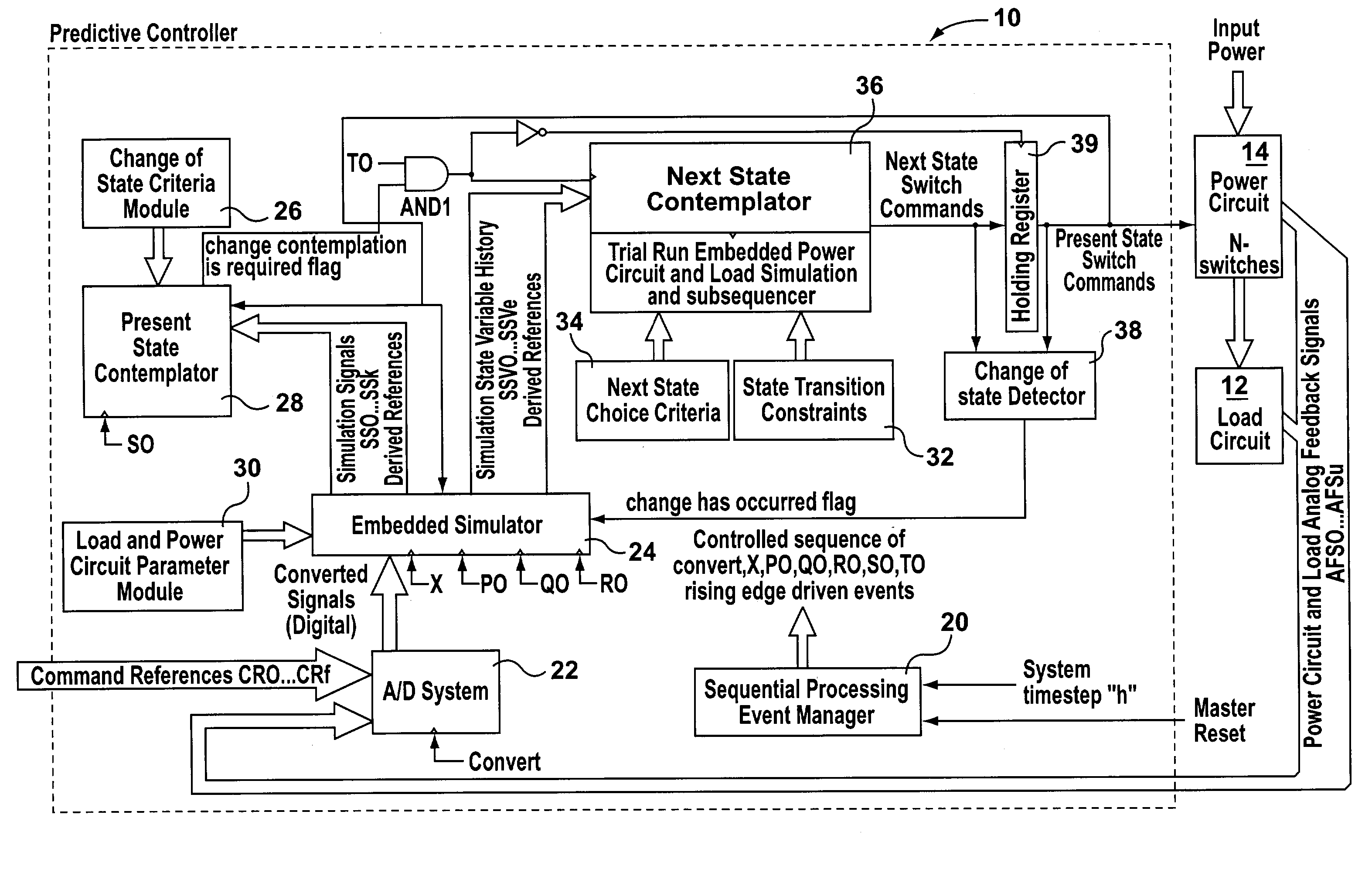
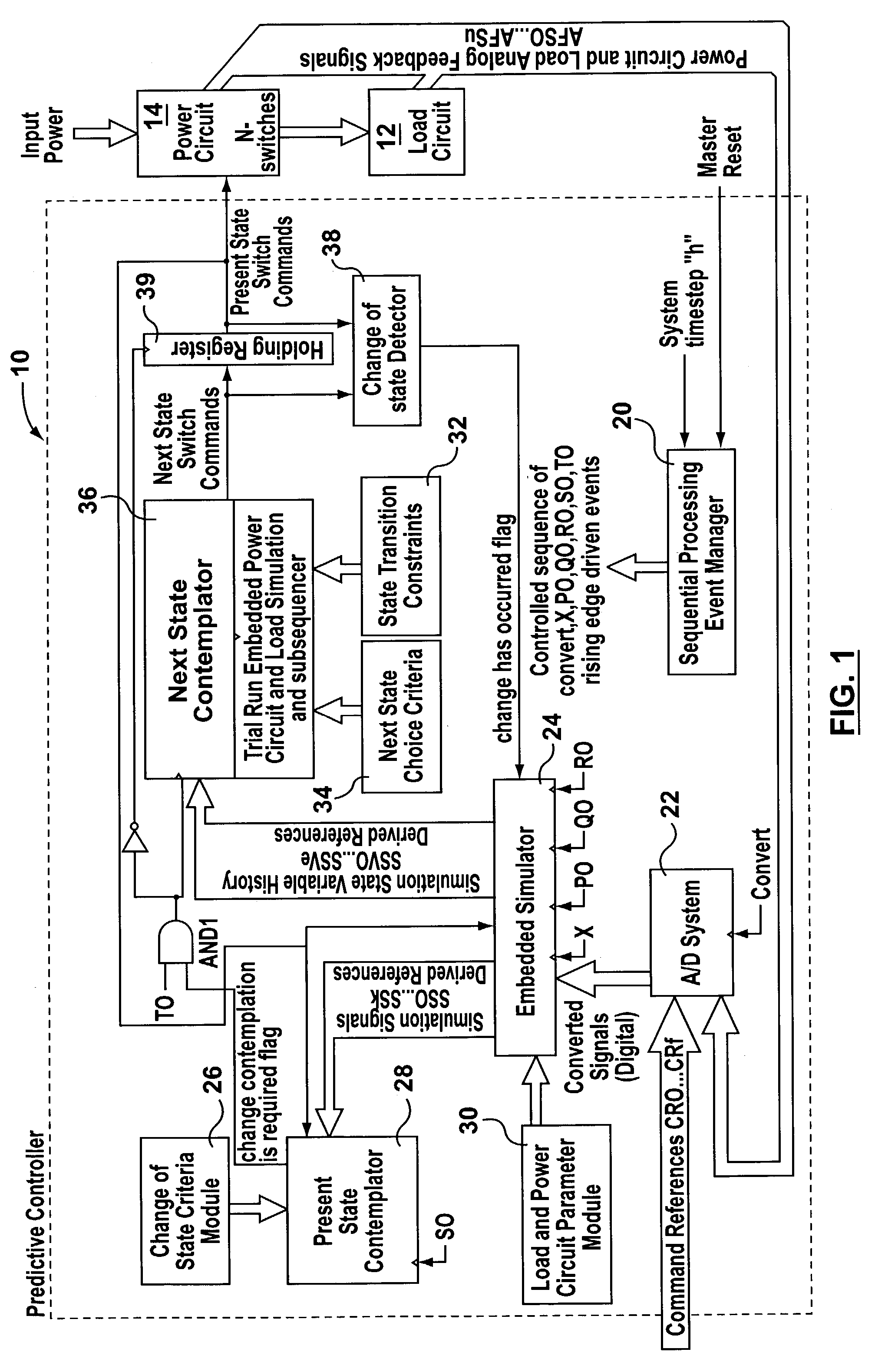
[0058]FIG. 1 is a block diagram illustrating a predictive control system 10, made in accordance with the invention. Control system 10 is designed to control the operation of a switchable power circuit 14 associated with a load circuit 12 using certain analog feedback variables from load circuit 12 as well as the switch configuration of power circuit 14 to achieve real time control on the basis of specified performance criterion. Control system 10 utilizes a finite state machine representation of the various switch states to model and predict the behaviour of load circuit 12 based on various possible switch states of power circuit 14 as switch state transitions are considered. Accordingly, control system 10 simulates real time operation of load circuit 12 in order to predictively select optimal switching states for power circuit 14.

[0059]Load circuit 12 can be any device or power process that involves switch-mode power control, such as motor drives, uninterruptible power supplies, co...


PUM


Abstract

A control system and method selects a switch configuration for a power circuit having N binary switches, based in part on a finite state machine. The control system includes an embedded simulator, and present and next state contemplators. The various switch states of the power circuit are modeled by the finite state machine such that at any time, the power circuit switches are in a Present State and there are a plurality of Next States which are one or more switch transitions away from the Present State. The embedded simulator estimates the operating conditions of the load based on measured operational characteristics and the Present State. The present state contemplator determines, based on the operating conditions, whether a switch state transition should be contemplated. If so, the next state contemplator determines the optimal next state based on performance criteria and sends a state switch command to the power circuit.

Description

CROSS-REFERENCE TO RELATED APPLICATIONS[0001]This application claims priority from U.S. Provisional Patent Applications Ser. No. 60 / 359,898 filed on Feb. 28, 2002 and Ser. No. 60 / 383,771 filed May 30, 2002.FIELD OF THE INVENTION[0002]This invention relates to a control system and method and more particularly to a control system and method that incorporates predictive techniques for application to a digital switching system.BACKGROUND OF THE INVENTION[0003]Traditional power electronic control systems using switch-mode principles are typically structured to accommodate the needs of an overall system that include a power circuit (actuator), a power load (plant), and a controller that controls the operation of the power circuit. Many of the overall system elements are non-linear, and possess numerous energy storage elements. Conventional simulation software allows designers to simulate the operation of the overall system so that a particular control system can be verified for proper fun...

Claims


Application Information

Patent Timeline
Patent Type & Authority Patents(United States)
IPC IPC(8): G06F19/00G05B19/00G06F17/50H02M7/162H02M7/5387H02P21/00
CPCG06F17/5036H02M7/53873H02P21/085H02P21/145Y02T10/82G06F30/367H02P21/09H02P21/16
Inventor RICHARDS, MICHAEL J.
Owner ZETACON CORP
Why Eureka
Try Eureka