
Apparatus and method for shearing reinforced concrete piles and metal piles and crushing reinforced concrete piles

a technology of reinforced concrete and equipment, applied in the field of equipment and methods for cutting and crushing reinforced concrete, can solve the problems of large man-hours, time-consuming and costly procedures, and slow and laborious methods, and achieve the effect of significant reducing ovate deformation

Active Publication Date: 2007-07-17
TODACK JAMES J
View PDF25 Cites 23 Cited by
  • Summary
  • Abstract
  • Description
  • Claims
  • Application Information

AI Technical Summary

Benefits of technology

"The present invention provides an apparatus and method for shearing and crushing columnar members, such as reinforced concrete piles and metal piles, that can be used in the construction industry for decommissioning offshore platforms. The apparatus has a frame with a cutter blade and hydraulic rams for movement between a retracted position and an extended position. The cutter blade has a double beveled profile for shearing and crushing the piles. The apparatus can be quickly and easily installed and requires fewer components and less servicing time than prior art apparatus. The invention also provides an apparatus for shearing and crushing reinforced concrete piles that does not require the use of explosives and can be used on land and offshore."

Problems solved by technology

These procedures are time consuming and costly.
This method is slow and labor intensive when multiple piles are involved.
When the exposure of the steel reinforcing strands or bars (rebar) within the piles is specified, the task of exposing the rebar is typically accomplished by jack hammering and chiseling, which requires extensive man-hours, with potential danger to the operator, depending on the location of the piles, and damage to the steel reinforcing by the jackhammer or chipping tool.
Reinforced concrete piles are also conventionally cut off or demolished using explosives, however, the use of explosives, particularly in demolishing bridge, pier and dock supporting piles, can have serious negative environmental effects encompassing the water environment and the marine life that typically congregate near piles and utilize the structures as a natural habitat.
As the straight beveled edge of the cutting blade becomes worn, it prevents the leading edge of the blade from making complete contact with the anvil face, thus potentially preventing the leading edge of the blade from completely severing all the steel strands and / or rebar.
One of the problems with the prior art pile crushing method, such as taught by these patents, is that it requires the removal of the shearing blade and the anvil abutment plate and the installation of a pair of opposed coplanar blades each having a cutting edge that matches the profile of one-half of the pile; thus, different sizes of coplanar blades would be required for crushing various different sizes and shapes of piles to achieve the desired result.
However, conventional mechanical cutting procedures are time consuming and expensive.
If there is concrete or grout between the casing and conductor or in the annulus between the pipes, the cutting is slowed down and the cutter may not work efficiently.
If there is concrete or grout between the casing and conductor or in the annuals formed by the two pipes, the cutter may not function properly.
The conventional mechanical cutting operations and use of divers is time consuming, expensive, and dangerous to the divers.
The use of explosives is often used for the removal of grouted well conductors or grouted piles, however, this technique can have serious deleterious environmental effects encompassing the marine environment and the living marine resources, such as sea turtles, marine mammals, and fish, that typically congregate near the platform and utilize the platform as a natural habitat.
A crack is formed in the pile in front of the blade edge, and the pile is broken by the bending moment.

Method used


Image

  • Apparatus and method for shearing reinforced concrete piles and metal piles and crushing reinforced concrete piles
  • Apparatus and method for shearing reinforced concrete piles and metal piles and crushing reinforced concrete piles
  • Apparatus and method for shearing reinforced concrete piles and metal piles and crushing reinforced concrete piles

Examples


Embodiment Construction

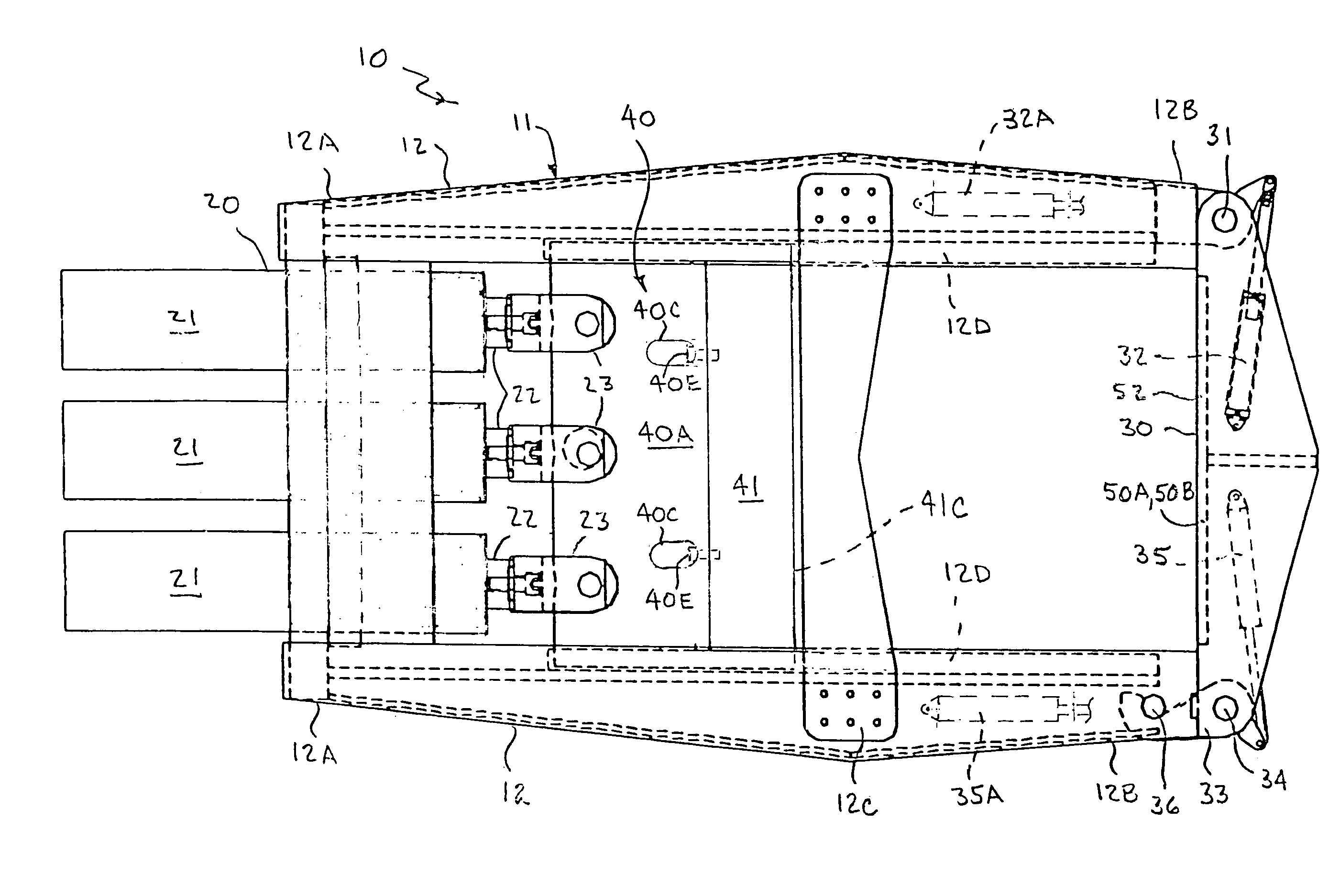
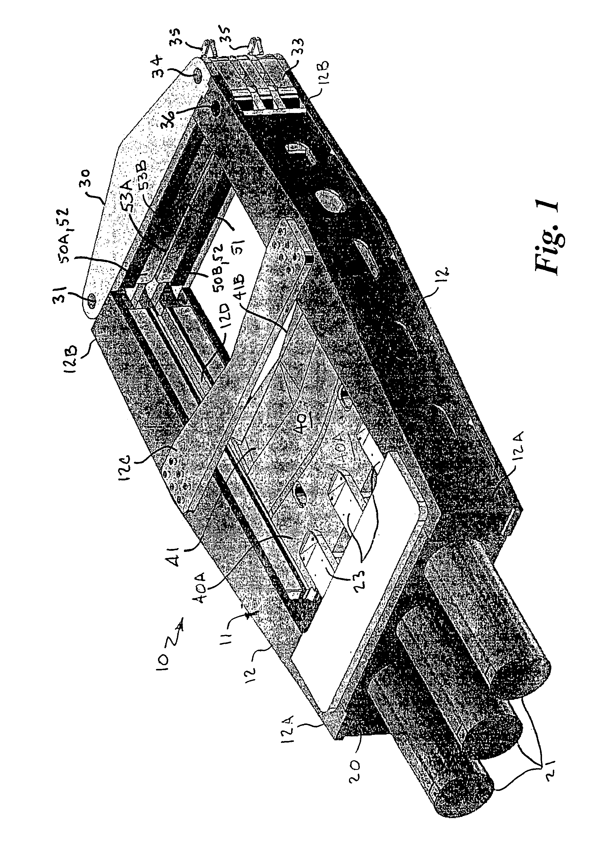
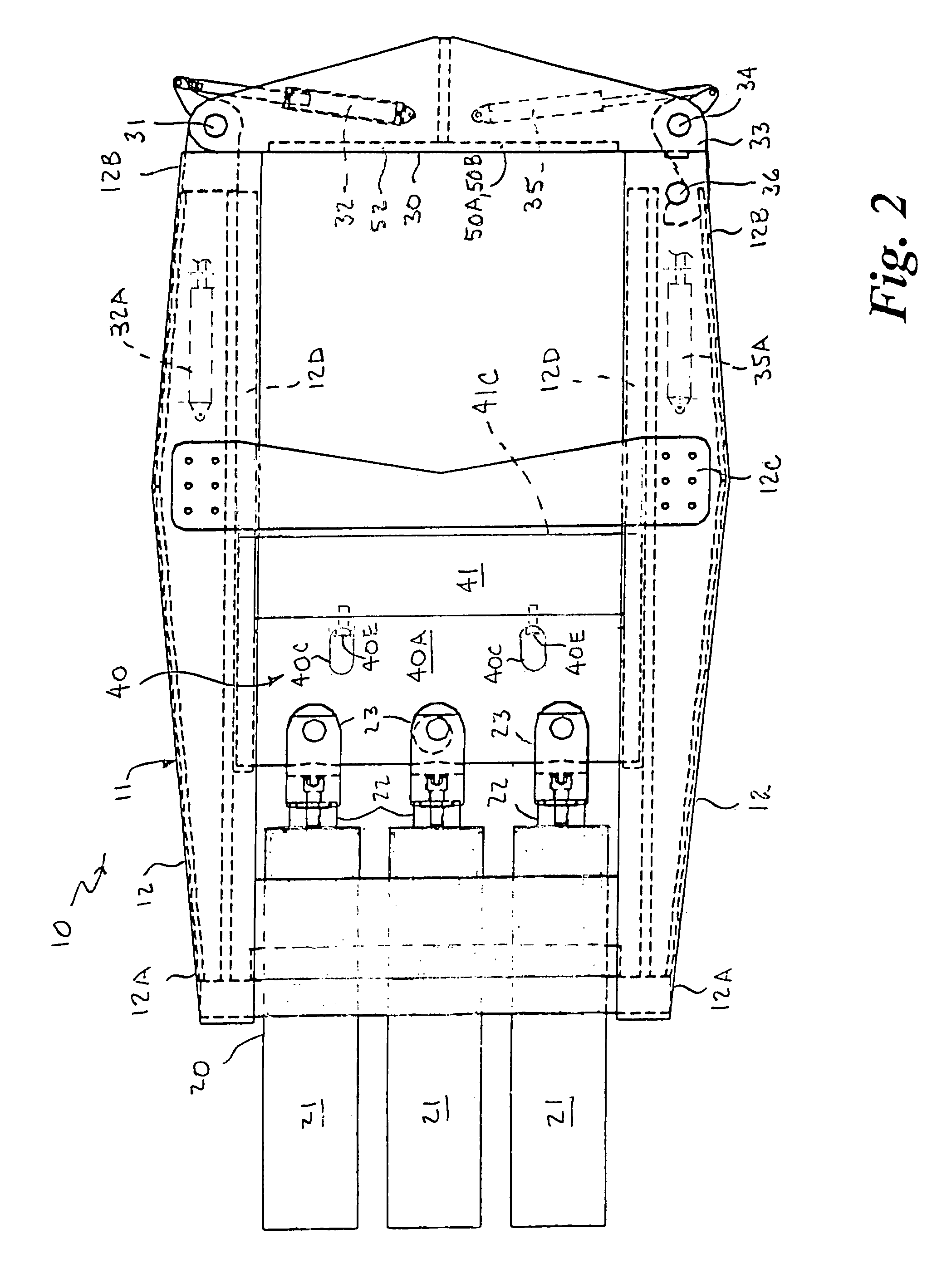
[0050]Referring to the drawings by numerals of reference, there is shown in FIGS. 1-5, a preferred apparatus 10 for shearing a reinforced concrete pile and the reinforcing steel strands or rebar embedded therein at a predetermined height. The apparatus includes a frame 11 having two parallel laterally spaced apart channel members 12 having opposed first and second ends 12A and 12B, a hydraulic ram support cross member 20 extending transversely between the first ends 12A, an abutment gate member 30 hingedly connected at the second ends 12B to extend transversely therebetween in a closed position, and intermediate channel support cross members 12C extending transversely between the channel members 12 intermediate the fist and second ends thereof.

[0051]A movable two-part cutter blade assembly 40 is slidably mounted transversely between the channel members 12 in guide rails 12D secured to the channel members and is slidable therein between a first or retracted position and a second or e...


PUM

PropertyMeasurementUnit
depthaaaaaaaaaa
depthaaaaaaaaaa
angleaaaaaaaaaa

Abstract

An apparatus (10) for shearing off reinforced concrete piles and metal piles, casing and conductor pipes, and crushing reinforced concrete piles has a frame (11) with first and second ends and a cutter blade (41) movably mounted on the frame driven by hydraulic rams (21) between a retracted position adjacent to the first end and an extended position toward the second end. An abutment gate (30) pivotally mounted and latched at the frame second end has vertically spaced first and second abutment surfaces (52A, 52B) and first and second horizontal shearing surfaces (53A, 53B) disposed in parallel vertically spaced relation defining an opening (51) therebetween through which the cutting edge (41B, 41C) of the blade passes. Removable crushing attachments (60A, 60B) allow crushing of concrete piles, and removable arcuate abutment attachments (54) accommodate cylindrical piles, casing and conductor pipes.

Description

CROSS REFERENCE TO RELATED APPLICATION[0001]This application claims priority of U.S. Provisional Patent Application Ser. No. 60 / 550,552 filed on Mar. 5, 2004.BACKGROUND OF THE INVENTION[0002]1. Field of the Invention[0003]This invention relates generally to pile cutting and crushing apparatus and methods, and more particularly, to an apparatus and method for shearing reinforced concrete piles, metal piles, casing and conductor pipe arrangements, and crushing reinforced concrete piles to expose reinforcing steel within the piling without damaging the structural integrity of the imbedded steel.[0004]2. Background Art[0005]As used herein, the term “columnar” is defined as resembling or having the form of a column. The term “pile” or “piling”, as used herein, means a long columnar member driven or installed into the earth or seabed to carry a vertical load or serve as a support or protection. The present invention has utility in the construction industry for shearing and crushing reinfo...

Claims


Application Information

Patent Timeline
Patent Type & Authority Patents(United States)
IPC IPC(8): B28D1/32B28D1/22
CPCB28D1/222Y10T83/8748Y10T83/8864Y10T83/9447
Inventor TODACK, JAMES J.
Owner TODACK JAMES J
Learn More