Encoder with absolute signal processing and incremental signal output and method of using such an encoder

an encoder and absolute signal technology, applied in the direction of optical conversion of sensor output, transmission system, calibration apparatus, etc., can solve the problems of virtual zero-travel approximately at standstill, and also not permitted, so as to increase the reliability and security of incremental measurement transmission.

Inactive Publication Date: 2007-07-17
RODI ANTON
View PDF9 Cites 10 Cited by
  • Summary
  • Abstract
  • Description
  • Claims
  • Application Information

AI Technical Summary

Benefits of technology

[0009]The inventive solution makes a useful contribution when it comes to facilitating the process of conversion to absolute encoder technology and makes the introduction of evolutionary design in incremental encoders for both encoder manufacturers as well as plant, machine, equipment and control manufacturers possible over the short term.
[0012]The embodiment according to this invention permits recording of the reference position at any time during the entire operation and to a large extent contributes toward increasing the reliability and security of incremental measurement transmissions far beyond known incremental measuring systems. Moreover, additional functions concerning position queries and multi-turn evaluations are made possible in order to thus extend the incremental measurement processing and to provide for the desired transition toward universal use of absolute rather than incremental encoders.

Problems solved by technology

Apart from the additional expenditure on electronics for implementing the method of the separate interface and the additional space required as well as the installation expenditure in the absolute encoder, the method together with its embodiment has clear disadvantages.
The method also only permits virtual zero-travel approximately at standstill if the errors through operating motion are to remain within the tolerable range.
Thus zero-travel is also not permitted even with low operating speeds, so that these must be reduced to the conditions of standing adjustment devices.
This is disadvantageous since generally during the entire operating sequence the primary control must constantly record and also process the incremental pulses without error and only permits examination with zero travel.
This is already in the critical range of industrial applications and represents an omission as regards this solution since it is precisely the recording of absolute measured values that permits constant monitoring of the position and cannot be arbitrarily used.

Method used


Image

  • Encoder with absolute signal processing and incremental signal output and method of using such an encoder
  • Encoder with absolute signal processing and incremental signal output and method of using such an encoder
  • Encoder with absolute signal processing and incremental signal output and method of using such an encoder

Examples


Embodiment Construction

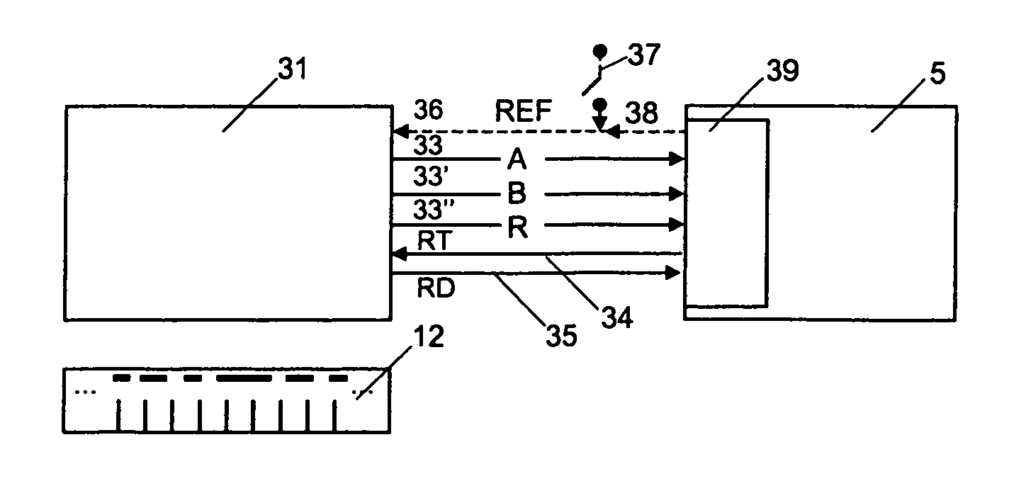
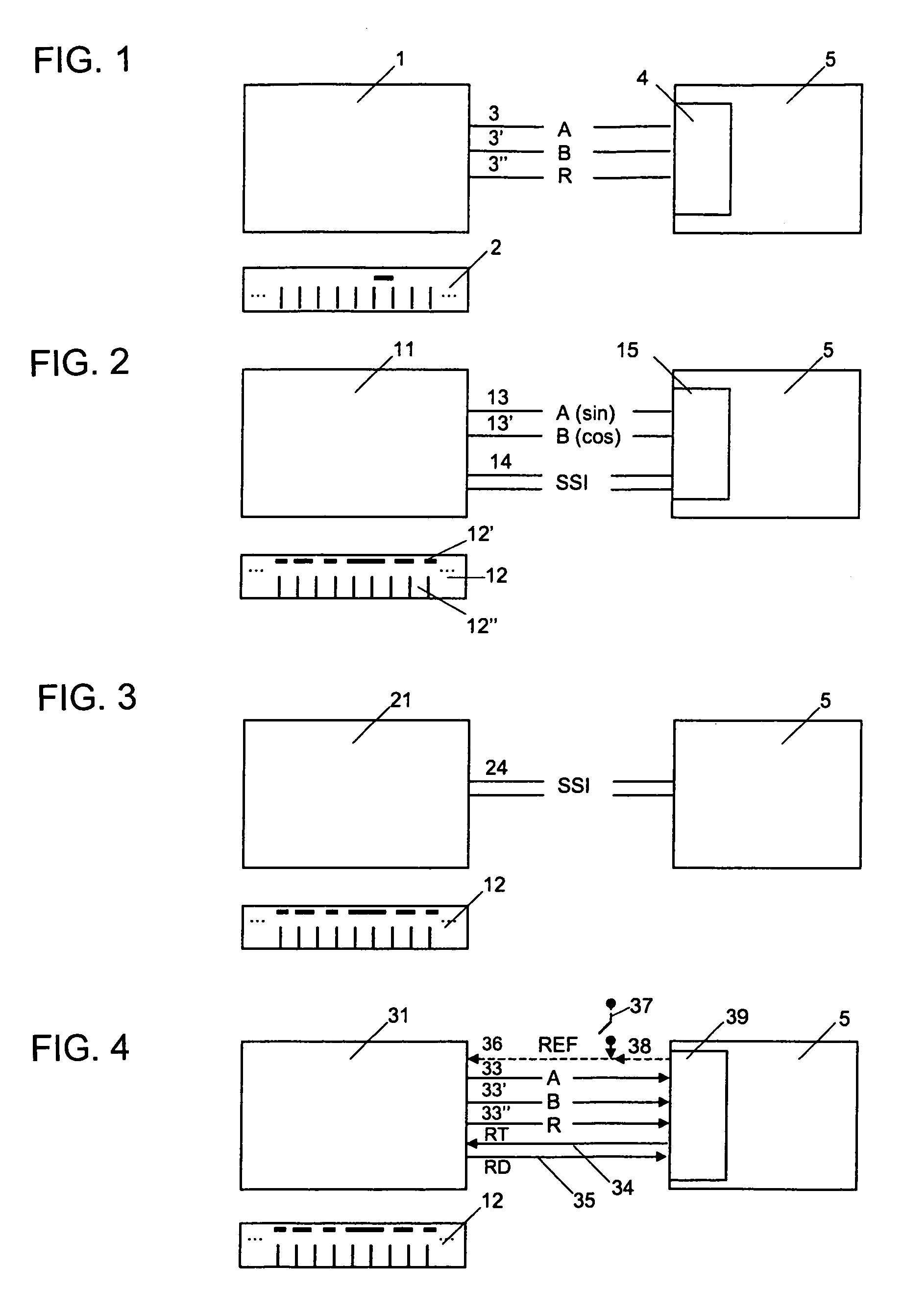
[0028]FIG. 1 shows a conventional encoder 1 with a scale 2 for incremental measurements and measurement processing 4 of the A-, B-, R-signals 3, 3′, 3″ in the primary control unit 5. From the A-, B-, R-signals the digital incremental signals (high, low) resulting from relative movement between the scale 2 and the encoder 1 are numerically recorded according to direction from a reference position and evaluated in the control unit to measured values for the actual position. It is customary to evaluate the incremental signals on the basis of a time reference, e.g. by means of an already existing clock-pulse generator or oscillator for synchronous signal evaluation with the digital logic in order to determine the adjustment speed of the measuring device. In the case of higher resolutions of the incremental measuring device, e.g. through analog signal transmission of A- / B-signals 3, 3′ in the sin / cos characteristic and highly accurate analog-digital conversion in measurement processing 4...


PUM


Abstract

An encoder device for the determination of absolute angle or linear segments is described, with which the distance from the actual to the reference position is determined upon prompting and output via incremental signals. This encoder offers new functions for the incremental measuring system employed up to now. The transition to the absolute measuring system is also made possible according to requirements.

Description

[0001]This invention was developed under Office of Naval Research Government Contract No. N00014-02-C-0250. The government may have certain rights in this invention.BACKGROUND OF THE INVENTIONFIELD OF THE INVENTION[0002]The invention relates to an encoder device for determining absolute angle and / or linear segments, more specifically an encoder device with absolute signal processing and incremental signal output, and a method for determining absolute angle and / or linear segments with such an encoder device.[0003]Two types of encoders for measuring angle and / or linear segments are familiar in industrial applications: incremental and absolute encoders.[0004]Incremental encoders record the incremental scales / measuring disks by means of a scanning device and then pass them on as incremental signals to a control unit for evaluation. The incremental signals are predominantly embodied in well-known semiconductor level signals with so-called A-, B- and R-tracks. The B-track is shifted appro...

Claims


Application Information

Patent Timeline
Patent Type & Authority Patents(United States)
IPC IPC(8): G01D5/34G01C17/38H03M1/22
CPCG01D5/2454G08C21/00H04Q9/14
Inventor RODI, ANTON
Owner RODI ANTON
Why Eureka
Try Eureka