
Voltage clamping circuit for a bicycle dynamo

a voltage clamping circuit and dynamo technology, applied in the field of bicycles, can solve the problems of high voltage bursts, high voltage, high cost, etc., and achieve the effect of accurately detecting speed and reducing thermally induced degradation of characteristics

Inactive Publication Date: 2007-07-17
SHIMANO INC
View PDF14 Cites 2 Cited by
  • Summary
  • Abstract
  • Description
  • Claims
  • Application Information

AI Technical Summary

Benefits of technology

[0012]Among other things, there is now provided an inexpensive circuit having minimal thermally-induced degradation of characteristics. Where speed pulses are generated using voltage generated by the dynamo, speed can be sensed accurately. Additional inventive features will become apparent from the description below, and such features alone or in combination with the above features may form the basis of further inventions as recited in the claims and their equivalents.

Problems solved by technology

Unfortunately, components designed to withstand high voltages lack general application and tend to be expensive as well.
Another difficulty arising from the generation of voltages from a dynamo is fluctuation in the electrical load connected to a dynamo which, in turn, can result in bursts of extremely high voltage, termed “surge voltage”.
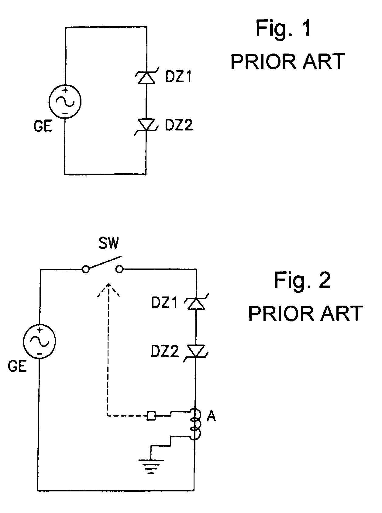
However, diodes Dz1 and Dz2 tend to generate heat, which can lead to problems in degraded characteristics.
However, such a circuit requires elements with high withstand voltage for the switch SW and sensor A controlling it.
Another drawback is the increased number of components required.
Furthermore, where a device is charged by the dynamo, failure to charge adequately may result from the operation of the switch.
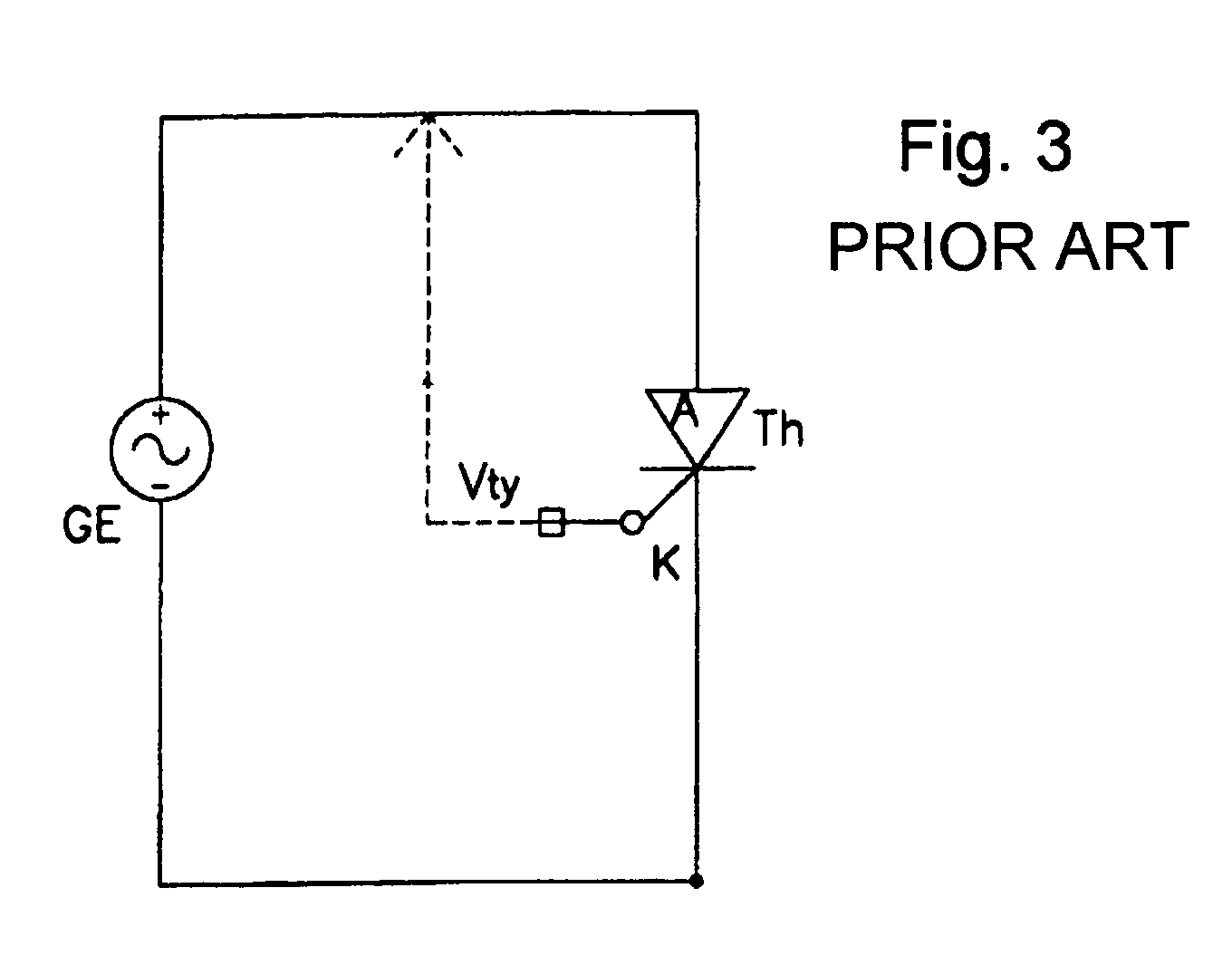
However, this circuit design has problems, particularly when the signal produced by the dynamo is used to generate pulses that indicate bicycle speed.
As a result, the pulse produced by decision voltage Vs will have a disturbed waveform like that shown at the bottom FIG. 4(c), thus making it impossible to sense speed accurately.

Method used


Image

  • Voltage clamping circuit for a bicycle dynamo
  • Voltage clamping circuit for a bicycle dynamo
  • Voltage clamping circuit for a bicycle dynamo

Examples


Embodiment Construction

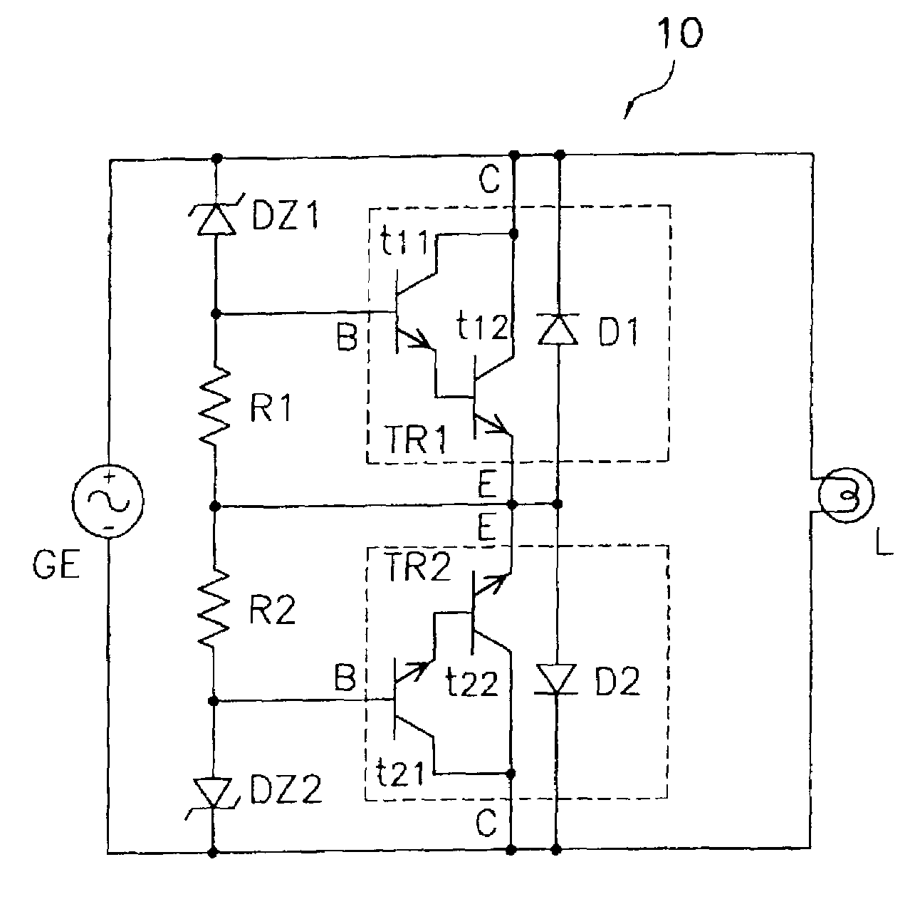
[0026]FIG. 5 is a schematic diagram of an embodiment of a voltage a clamping circuit 1 with inventive features. This voltage clamping circuit 1 comprises a bridge circuit Db connected to a dynamo GE, and a load L such as a headlamp. Dynamo GE may be a hub dynamo integrally provided in a hub of the bicycle. Bridge circuit Db has four diodes connected to provide full wave rectification of the output of dynamo GE. Clamping circuit 1 clamps the output voltage of bridge circuit Db to a predetermined voltage (clamping voltage) and supplies the clamping voltage to the load L. Clamping circuit 1 includes a power transistor circuit TR1. A Zener diode DZ1 and a resistor R1 are provided for controlling the on / off operation of transistor circuit TR1.

[0027]Transistor circuit TR1 includes two NPN bipolar transistors t1, t2 connected in series (a Darlington connection in this example). Transistor circuit TR1 also is connected in parallel with headlamp L. In this example, the collector of transisto...


PUM


Abstract

A voltage clamping circuit comprises a first high current gain circuit adapted to receive current from the first line; and a first switching circuit that turns on the first high current gain circuit to flow current away from the first line when the first switching circuit senses a first voltage from the first line above a clamping voltage, and turns off the first high current gain circuit when the first switching circuit senses the first voltage below the clamping voltage.

Description

BACKGROUND OF THE INVENTION[0001]The present invention is directed to bicycles and, more particularly, to various inventive features of a circuit used with bicycle dynamos.[0002]Bicycles are equipped with dynamos for the purpose of illuminating headlamps, powering electrical components, and so on. The voltage generated by a dynamo is typically proportional to the speed of the bicycle which, in turn, is determined by the rate of rotation of the wheels. At high speed, the voltage can exceed 100 V in some instances. It is therefore necessary to design electrical components powered by the voltage generated by the dynamo to be able to withstand such high voltage. Unfortunately, components designed to withstand high voltages lack general application and tend to be expensive as well.[0003]Another difficulty arising from the generation of voltages from a dynamo is fluctuation in the electrical load connected to a dynamo which, in turn, can result in bursts of extremely high voltage, termed ...

Claims


Application Information

Patent Timeline
Patent Type & Authority Patents(United States)
IPC IPC(8): H03K5/08H03L5/00B62J6/02H02H9/04H02M7/12H02P9/30H02P9/48
CPCH02H9/041
Inventor UNO, KOUJI
Owner SHIMANO INC
Learn More