Zoom lens and image pickup

a zoom lens and image pickup technology, applied in the field of zoom lens and image pickup apparatus, can solve the problems of insufficient inability to ensure the distance forward and backward of the aperture stop, and inability to correct the negative distortional aberration which appears in the wide angle end state appropriately, so as to suppress the degradation of performance upon image shifting and achieve good focus state. , the effect of miniaturization of the zoom lens

Inactive Publication Date: 2007-07-17
SONY CORP
View PDF8 Cites 8 Cited by
  • Summary
  • Abstract
  • Description
  • Claims
  • Application Information

AI Technical Summary

Benefits of technology

[0023]It is an object of the present invention to provide a zoom lens and an image pickup apparatus which are superior in reduction of the lens diameter and can suppress degradation in performance while a high zoom ratio is achieved.
[0031]Also with the image pickup apparatus, the image is shifted and degradation in performance upon image shifting is suppressed by shifting the positive sub group of the third lens group. Further, miniaturization of the zoom lens can be anticipated.
[0032]Preferably, the image pickup apparatus further comprises a hand shake detection section for detecting a blur of the image pickup element, a hand shake control section for calculating a blur correction angle for correcting an image blur by the shake of the image pickup element detected by the hand shake detection section and signaling a driving signal for positioning the positive sub group of the third lens group at a position based on the blur correction angle, and a hand shake driving section for receiving the driving signal signaled from the hand shake control section and shifting the positive sub group in a direction perpendicular to the optical axis based on the received driving signal. With the image pickup apparatus, a blur of an image by a shake of the image pickup element by a hand shake or the like can be corrected, and a good focused state can be obtained. Consequently, an image of high quality whose various aberrations are corrected favorably can be acquired by the image pickup apparatus.

Problems solved by technology

However, the conventional zoom lenses described above have the following problems where it is intended to achieve a high power variation ratio and a high performance.
Therefore, negative distortional aberration which appears in a wide angle end state cannot be corrected appropriately.
However, this increases the lens diameter of the first lens group, resulting in failure in sufficient miniaturization of the zoom lens.
Where the positive sub group disposed on the object side of the third lens group is shifted, the distances forwardly and backwardly of the aperture stop cannot be assured sufficiently, and this gives rise to interference with an iris mechanism section.
Where the positive sub group disposed on the image side of the third lens group is shifted, if it is tried to raise the power variation ratio, then the shift amount of the positive sub group becomes very large, which gives rise to a problem of increase in scale of the driving mechanism and complication of the structure.

Method used


Image

  • Zoom lens and image pickup
  • Zoom lens and image pickup
  • Zoom lens and image pickup

Examples


first embodiment

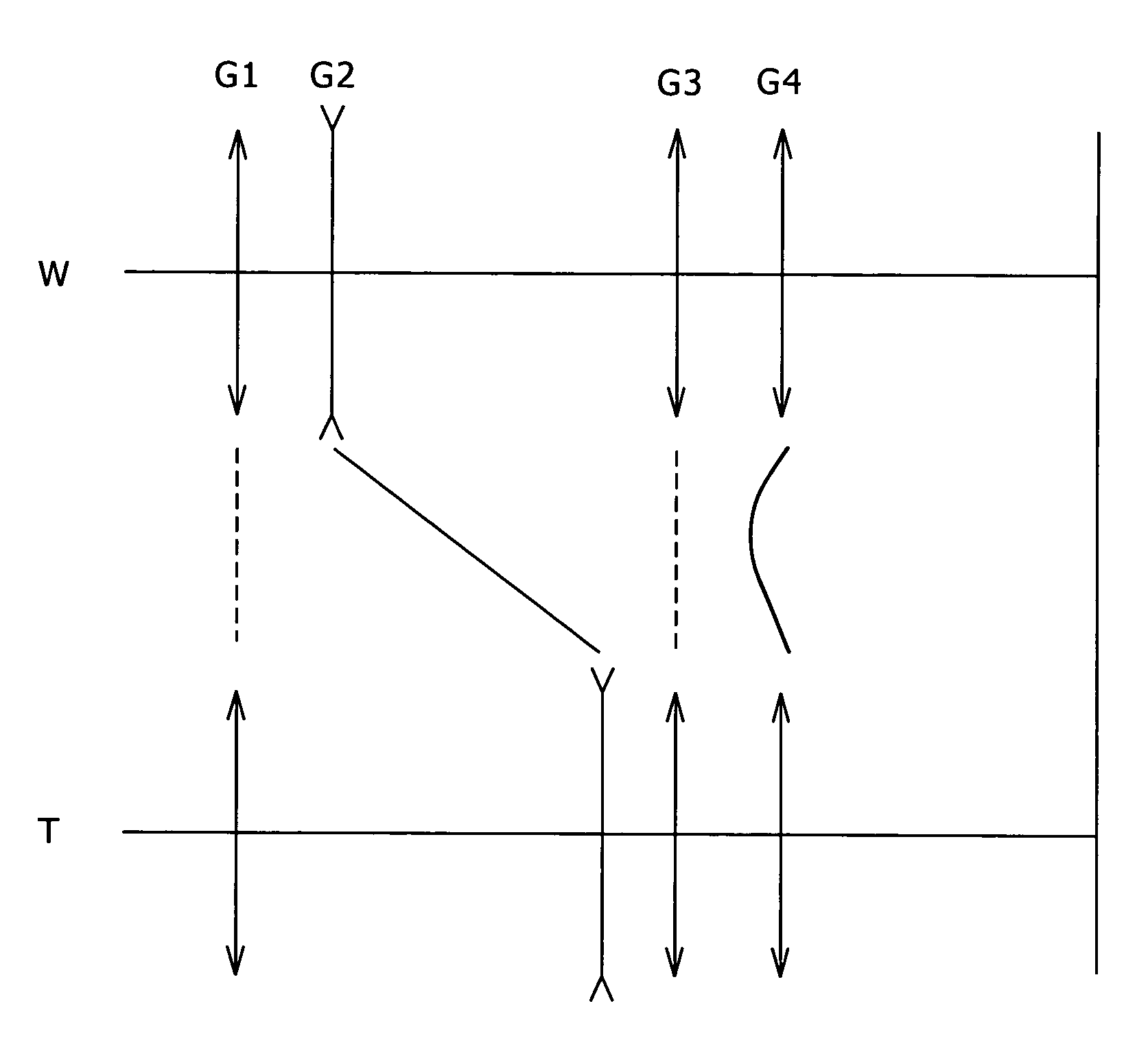
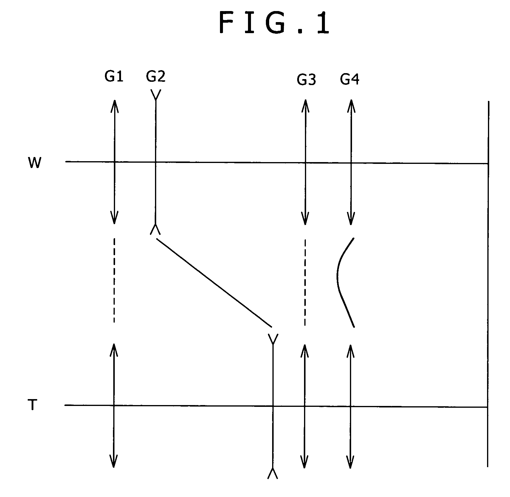
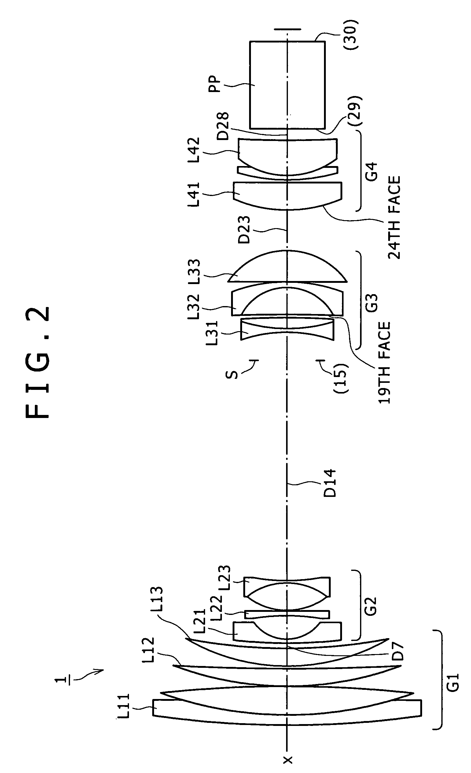
[0133]FIG. 2 shows a lens configuration of a zoom lens according to the present invention. Referring to FIG. 2, the first lens group G1 includes a cemented lens L11 of a negative lens of a meniscus shape having a convex face directed to the object side and a positive lens having a convex face directed to the object side, a positive lens L12 having a convex face directed to the object side, and a positive lens L13 having a convex face directed to the object side. The second lens group G2 includes a negative lens L21 of a meniscus shape having a concave face directed to the image side, a negative lens L22 having a biconcave shape, and a cemented lens L23 of a biconvex lens and a biconcave lens. The third lens group G3 includes a cemented negative lens L31 of a biconcave lens and a positive lens having a convex face directed the object side, a cemented lens L32 of a biconvex lens having an aspheric face on the object side and a negative lens having a concave face directed to the object...

second embodiment

[0148]FIG. 9 shows a lens configuration of a zoom lens according to the present invention. Referring to FIG. 9, the first lens group G1 includes a cemented lens L11 of a negative lens of a meniscus shape having a convex face directed to the object side and a positive lens having a convex face directed to the object side, a positive lens L12 having a convex face directed to the object side, and a positive lens L13 having a convex faced directed to the object side. The second lens group G2 includes a negative lens L21 of a meniscus shape having a concave face directed to the image side, a negative lens L22 having a biconcave shape, and a cemented lens L23 of a biconvex lens and a biconcave lens. The third lens group G3 includes a cemented negative lens L31 of a biconcave lens and a positive lens having a convex face directed to the object side, a cemented lens L32 of a biconvex lens having an aspheric face on the object side and a negative lens having a concave face directed to the ob...

third embodiment

[0163]FIG. 16 shows a lens configuration of a zoom lens according to the present invention. Referring to FIG. 16, the first lens group G1 includes a cemented lens L11 of a negative lens of a meniscus shape having a convex face directed to the object side and a positive lens having a convex face directed to the object side, a positive lens L12 having a convex face directed to the object side, and a positive lens L13 having a convex face directed to the object side. The second lens group G2 includes a negative lens L21 of a meniscus shape having a concave face directed to the image side, a negative lens L22 having a biconcave shape, and a cemented lens L23 of a biconvex lens and a biconcave lens. The third lens group G3 includes a cemented negative lens L31 of a biconcave lens and a positive lens having a convex face directed to the object side, a cemented lens L32 of a biconvex lens having an aspheric face on the object side and a negative lens having a concave face directed to the o...


PUM


Abstract

A zoom lens is disclosed which is superior in reduction of the lens diameter and can suppress degradation in performance while a high zoom ratio is achieved. The zoom lens is formed as a zoom lens of a four-group configuration having positive, negative, positive and positive groups. The second and fourth lens groups move whereas the first and third lens groups are fixed. An aperture stop is disposed on the object side of the third lens group. The third lens group includes negative and positive sub groups with an air distance left therebetween. The positive sub group is shiftable perpendicularly to the optical axis to shift an image substantially perpendicularly. A conditional expression 1.4<|f3n| / f3<3 is satisfied where f3n is the focal distance of the negative sub group and f3 is the focal distance of the third lens group.

Description

CROSS REFERENCES TO RELATED APPLICATIONS[0001]The present invention contains subject matter related to Japanese Patent Application P2005-183207 filed with the Japanese Patent Office on Jun. 23, 2005, the entire contents of which being incorporated herein by reference.BACKGROUND OF THE INVENTION[0002]This invention relates to a novel zoom lens and image pickup apparatus, and more particularly to a zoom lens and an image pickup apparatus which have a hand shake correction function and suppress deterioration of a performance which occurs upon image shifting while the variation power is high.[0003]Conventionally, as a recording method of a camera, a method is known wherein a subject image formed on a surface of an image pickup device formed using a photoelectric conversion element such as a CCD (Charge Coupled Device) or a CMOS (Complementary Metal-Oxide Semiconductor) element is recorded by converting light amounts of the subject image into electric outputs by means of the photoelectri...

Claims


Application Information

Patent Timeline
Patent Type & Authority Patents(United States)
IPC IPC(8): G02B15/14
CPCG02B15/173G02B27/646G02B15/144113
Inventor OHTAKE, MOTOYUKI
Owner SONY CORP
Why Eureka
Try Eureka