

DC backup power supply device and method for diagnosing the same
- Summary
- Abstract
- Description
- Claims
- Application Information
AI Technical Summary
Benefits of technology
Problems solved by technology
Method used
Image

Examples
first embodiment
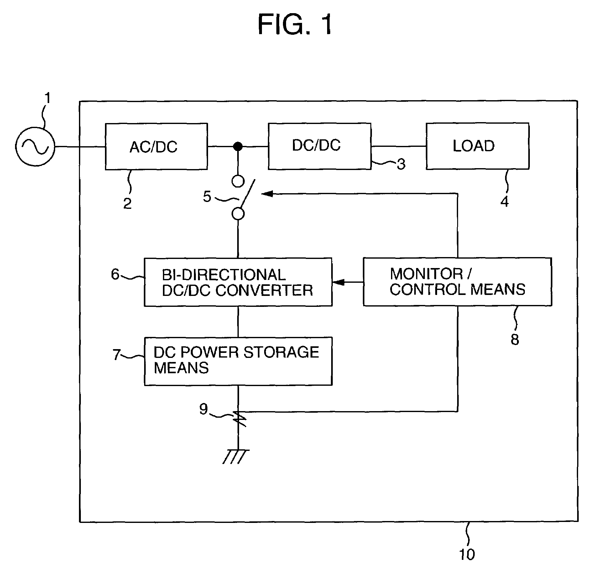
[0022]FIG. 1 shows a block diagram of a DC backup power supply device in accordance with the present invention. A power from a commercial AC power source 1 is converted to a DC power by an AC / DC converter 2 provided within an electric apparatus 10. The DC power is input to a DC / DC converter 3, having a voltage control function to be supplied to a load 4, forming a main circuit. A DC backup power supply device includes, as major constituent elements, a bi-directional DC / DC converter 6 connected to a DC path between the converters of the main circuit via a switch 5 and a DC power storage 7 such as a secondary battery. For the purpose of controlling the switch 5 and bi-directional DC / DC converter 6, a monitor / control 8 is provided to input an electrical signal from a circuit 9 or the like for detecting a charging / discharging current of the DC power storage 7 and to monitor and control the charging or discharging of the DC power storage 7.
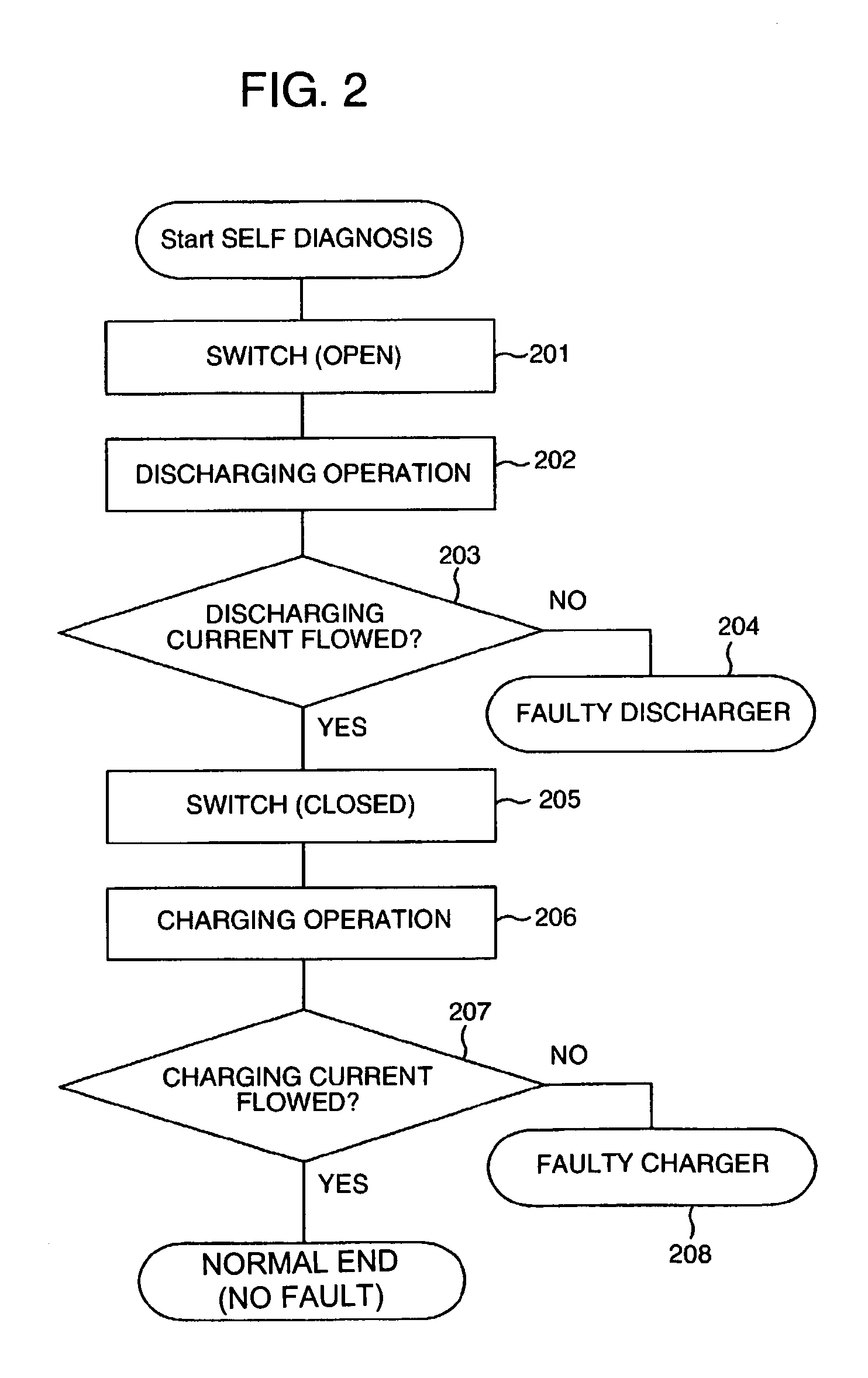
[0023]FIG. 2 is a processing flowchart of a self...
second embodiment
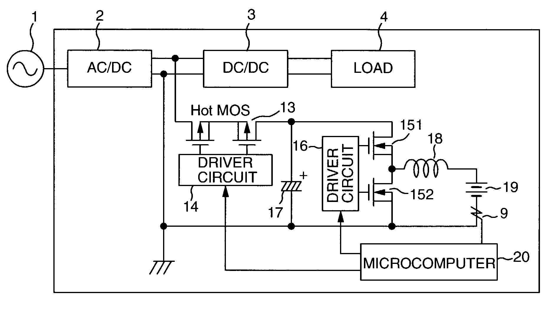
[0029]FIG. 4 shows a specific circuit of the DC backup power supply device in accordance with the present invention. In this embodiment, in addition to the embodiment of FIG. 3, a second switch (battery MOS FET) 21 is provided between the bi-directional DC / DC converter and the battery 19 to be connected with a driver circuit 22 for driving the second switch and to be controlled by the microcomputer 20.
[0030]With the present arrangement, since the battery MOS FET 21 is turned ON / OFF controllably under control of the microcomputer 20, an excessive current caused by an abnormality or the like in the voltage step-up / down choppers can be prevented from flowing through the battery 19. For example, when a short-circuiting occurs in the smoothing capacitor 17 or in the MOS FET 151, by turning OFF the second switch (battery MOS FET) 21, the circuit can be prevented from being damaged by the excessive current from the battery 19.
[0031]FIG. 5 is a second embodiment of a processing flowchart of...
third embodiment
[0034]FIG. 6 is a specific circuit of the DC backup power supply device according to the present invention The present embodiment is different from the embodiment of FIG. 4 in that a circuit 23 for detecting a total voltage (voltage across both terminals) of the battery 19 is provided and the detected voltage is applied to the microcomputer 20. With the present arrangement, upon diagnosis, the device can measure not only the charging / discharging currents of the battery in its charging, discharging and standby modes, but also the voltage of the battery. As a result, the device can measure an internal resistance r of the battery according to an equation which follows with use of three types of measured data: a battery voltage Vo prior to charging operation, a battery voltage Vc after the charging operation and a charging current Ic.
r=(Vc−Vo) / Ic
[0035]When the internal resistance of the battery is measured in this way, the deterioration diagnosis of the battery can be realized. In the ...
PUM
 Abstract
Description
Claims
Application Information